background image

42

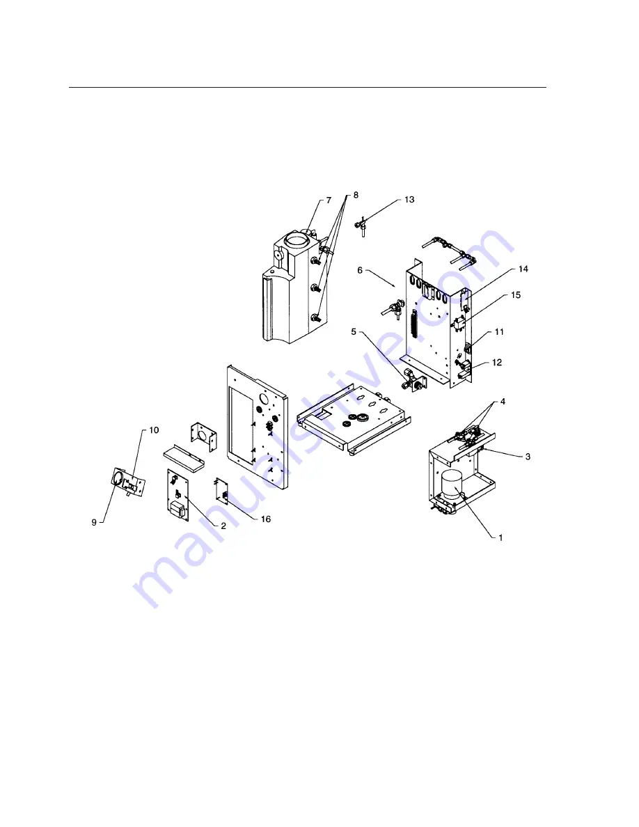
EASYpure RO Exploded View

Summary of Contents for EASYpure D7421

Page 1: ...ALLATION OPERATION SERVICE AND REPAIR MANUAL AND PARTS LIST LT742X16 8 20 97 Model Voltage D7421 120 D7422 240 D7422 33 230 D7423 100 Low Pressure D7428 120 Low Pressure D7429 240 Low Pressure D7429 3...

Page 2: ...2 Figure 1 EASYpure RO Ventgard Back Door Latch Pressure Gauge Indicator LED s Tank Water Level Sight...

Page 3: ...uipment Supplied By the EASYpure RO 15 Installing The Prefilter and Membranes 16 Prefilter Installation 16 Membrane Installation 17 Electrical Connections 20 Membrane Flush 20 Set Replace Prefilter In...

Page 4: ...urrent handling capacity 2 Do not mount the EASYpure RO directly over equipment that requires electrical service Routine maintenance of this unit may involve water spillage and subse quent electrical...

Page 5: ...els of chemical containers and Material Safety Data Sheets M S D S 5 Refer servicing to qualified personnel C To ensure safe mounting 1 Wall composition and construction as well as fastener type must...

Page 6: ...ery water temperature and water composition Listed membrane performance for a new membrane is based on optimum operating conditions of 60 psig 15 recovery 25 C 77 F feedwater tempera ture and feedwate...

Page 7: ...al equipment for measure ment control and laboratory use Part 1 General Requirements per the provisions of the Electromagnetic Compatibility Directive 89 336 EEC as amended by 92 31 EEC and 93 68 EEC...

Page 8: ...ckaging prior to dis carding the packaging 1 EASYpure RO Ventgard air filter 2 Power cord 3 Pump interlock cord 4 Membrane bypass tubing The following items are located inside the mem brane access doo...

Page 9: ...internal float switches will control the operation of the system If the EASYpure RO is to be used with the accesso ry 30 Liter Reservoir the reservoir must not be mounted farther than 4 feet away from...

Page 10: ...er D7424 must be added to the EASYpure RO to ensure automatic opera tion Install the EASYpure RO Bench Stand as follows 1 Remove the 4 feet from the EASYpure RO and retain the screws 2 Place the EASYp...

Page 11: ...will mate with the EASYpure RO INSTALLATION Figure 2 Wall Mounting the EASYpure RO Wall composition and con struction as well as fastener type must be considered when mounting this unit The mounting s...

Page 12: ...disconnect insert on one end and a 3 8 O D X 1 4 NPT tubing adapter on the other 2 Insert the quick disconnect insert into the feedwater inlet on the EASYpure RO See Figure 3 for location Install the...

Page 13: ...nd Figure 3 for fitting location 2 Thread the nut grab ring and backup ring on the reject adapter Do not use the o ring at this time 3 Push the tubing through the hex nut until it bottoms out in the a...

Page 14: ...ng adapter to permanently install the reject water tubing in the drain Tank Overflow Connection 1 Refer to Figure 3 and attach a cus tomer supplied hose barb connec tor and 5 8 O D tubing to the tub i...

Page 15: ...uctions in that unit s manual 3 Locate the pump interlock cord supplied with the EASYpure RO Plug one end of the pump interlock cord into the pump interlock on the EASYpure RO See page 11 Remove the j...

Page 16: ...oks 3 Lift the front of the door latch and open door Prefilter Installation Chlorine and particulates will damage your membranes resulting in premature mem brane failure Therefore your EASYpure RO use...

Page 17: ...4 Lower the prefilter and insert the lower end cap into the lower center socket until it is firmly seated Membrane Installation 1 Remove the membrane bypass tubing from the EASYpure RO see Figure 5 Th...

Page 18: ...e o ring back up ring stainless steel grab ring and nut are in place on the product and reject tubing on the EASYpure RO see Figure 4 page 12 Ensure that the product tube is connected to the product c...

Page 19: ...in the lower right hand socket 7 Remove the second RO membrane car tridge Part Number D7425 from its plas tic bag Install the second membrane in the left hand membrane position following the instructi...

Page 20: ...our EASYpure RO Direct the product water tubing to drain If you are feeding an accessory 30 Liter Reservoir disconnect the product water tubing from the accessory 30 Liter Reservoir Direct the product...

Page 21: ...ervoir Reconnect the pump interlock cord to the other EASYpure unit Set Replace Prefilter Indicator The extruded carbon prefilter both filters particu lates and absorbs free chlorine out of your feedw...

Page 22: ...the unit until the front of the door latch unhooks 4 Lift the front of the door latch and open door 5 Locate the switch panel on the upper left sidewall of the membrane compartment See Figure 9 for l...

Page 23: ...in top in bottom in top in More than 1 40 ppm top in bottom in top in top in Close and latch the membrane access door Your EASYpure RO is now ready for operation INSTALLATION Factory set Figure 10 Sw...

Page 24: ...l start up the pressure gauge will briefly indicate the feedwater pressure Once the pump starts the pressure gauge will indicate the pres sure after the pump which is the pressure on the reverse osmos...

Page 25: ...nergize the pump This switch senses the pressure after the prefilter and before the pump The EASYpure RO system will try to restart after it initially senses low pres sure If it senses low pressure th...

Page 26: ...percent rejection rate of the membrane falls below 65 the light will illuminate indicating membrane difficulty In most cases replacement of the membranes is called for Refer to troubleshooting guide...

Page 27: ...drawoff valve auxiliary drawoff on NANOpure and allowing water to flow until no more exits the unit Disconnect the EASYpure unit or NANOpure from the power supply 2 Close the inlet valve on the EASYpu...

Page 28: ...ne inlets a Wet the o rings on the connectors of the bypass tubing b Insert the connectors into the two membrane inlets Ensure that the metal clamps line up with the slots located on the floor of the...

Page 29: ...tom membrane bypass tubing assemblies and retain them for future use Remove the sanitization cartridge and discard it 14 Install a new pretreatment cartridge Reinstall existing membrane cartridges if...

Page 30: ...from the storage tank A Ventgard may be stored in a cool dry place almost indefinitely provided the plastic bag has not been opened Take the old Ventgard off the top of the EASYpure RO and install a f...

Page 31: ...e 5 After 3 minutes the flush solenoid valve closes and the EASYpure RO begins mak ing product water and sending it to the storage reservoir 6 The unit begins to monitor membrane per formance and the...

Page 32: ...sor tracks operating time and at pre selected intervals illuminates the replace filter light signifying that the carbon cartridge should be replaced 8 When the reservoir is full and the EASYpure RO is...

Page 33: ...ctors will determine the service life of your EASYpure RO membranes With proper main tenance the membranes should last approximately one year for normal usage When either the Service Membrane or the R...

Page 34: ...e EASYpure RO from its power source 2 To replace the prefilter remove the old prefilter then follow the proce dures in Prefilter Installation to install a new one 3 After you replace the prefilter pre...

Page 35: ...e filters resin cartridges etc and other items of limited service life indicator lights fuses etc that you can expect to replace on a more or less random basis Wherever possible Barnstead Thermolyne r...

Page 36: ...SAFETY STOCK Description Cat No Quantity Pump 100 volt low pressure PU742X3A 1 Pump 120 volt PU742X1A 1 Pump 120 volt low pressure PU742X3A 1 Pump 230 volt PU742X2A 1 Pump 230 volt low pressure PU742X...

Page 37: ...this unit or can be obtained promptly from the factory When service or replacement parts are needed we ask that you check first with your dealer If the dealer cannot handle your request then contact...

Page 38: ...ce prefilter Solenoid valve not open Replace solenoid valve Feed pressure below specification Increase pressure Illumination of service membrane light Decrease in rejection Improperly installed membra...

Page 39: ...39 Wiring Diagrams Figure 14 Wiring Diagram 100 Volt...

Page 40: ...40 WIRING DIAGRAMS Figure 15 Wiring Diagram 120 Volt...

Page 41: ...41 WIRING DIAGRAMS Figure 16 Wiring Diagram 230 Volts...

Page 42: ...42 EASYpure RO Exploded View...

Page 43: ...120 Volt RY631X3A Solenoid Valve 230 Volt RY631X3A Solenoid Valve 240 Volt 5 02280 Pressure Regulating Valve 6 PMX101 Reject Flow Regulating Orifice on side of rear case 7 PM703X7A Overflow Valve 8 SW...

Page 44: ...e of their susceptibility to overheating and con tamination must be returned to our factory and if upon inspection it is concluded that fail ure is not due to excessive high temperature or contaminati...

Reviews: