background image

8

SECTION F: SERVICE AND REPAIR

NOTE:

 All item numbers in ( ) refer to Figures 9 & 10.

WARNING ! - Before servicing and/or removing 
pump from system, verify that the piping system 
has no pressure.

F-1) Lubrication:

Anytime the pump is removed from operation the cooling oil 
in the motor housing (2) and seal chamber, must be checked 
visually for oil level and contamination.

F-1.1) Checking Oil:
Motor Housing -

 To check oil, set unit upright. Remove cap 

screws (6), lift conduit box assembly (10) from motor hous-
ing (2) but 

DO NOT

 disconnect conduit box wiring from motor 

leads. With a fl ashlight, visually inspect the oil in the motor 
housing (2) to make sure it is clean, clear and that oil level is 
above all internal componentry.

Seal Chamber -

 Place pump on its side with the square head 

pipe plug (22) downward (180° from discharge on bearing 
bracket 21), remove pipe plug (22) and drain oil from the seal 
chamber. If the oil is found to contain considerable water or 
other contamination or little oil drains out, the shaft seal (46) 
and diaphragm (32) should be inspected and replaced if 
required.

F-1.2) Testing Oil:

1.   Place pump on it’s side, remove cap screws (6), lift
 

conduit box assembly (10) from motor housing (2) and


drain oil into a clean, dry container. In separate 


container drain seal chamber by removing pipe plug (22).

2.  Check oil for contamination using an oil tester with a
 

range to 30 Kilovolts breakdown.

3.  If oil is found to be clean and uncontaminated (measure
 

above 15 KV. breakdown), refi ll the motor housing


and seal chamber as per section F-1.3.

4.  If oil is found to be dirty or contaminated (or measures
 

below 15 KV. breakdown), the the pump must be


carefully inspected for leaks at the shaft seal (46), 


conduit box assembly (10), diaphragm (32), O-rings (42),


pipe plugs (22) and (45) and pressure valve (5) before


refi lling with oil. To locate the leak, perform a pressure


test as per section F-1.4. After leak is repaired, refi ll with


new oil as per section F-1.3.

F-1.3) Replacing Oil:
Motor Housing -

 Drain all oil from motor housing and 

dispose of properly. Refi ll with (see parts list for amount) new 
cooling oil as per Table 1. An air space must remain in the top 
of the motor housing to compensate for oil expansion (see 
Fig. 9). Set unit upright and fi ll only until the motor, as viewed 
through the conduit box opening, is just covered and no 
more. Reassemble the O-ring (11), conduit box assembly (10) 
and cap screws (6), apply thread locking compound to each 
cap screw (6) thread before installing. Torque cap screws (6) 
to 15 ft., lb.

Seal Chamber -

 Refi ll chamber completely full with new 

cooling oil per Table 1 or reuse the uncontaminated oil.

WARNING !  - DO NOT overfi ll oil. 
Overfi lling of motor housing with oil can 
create excessive and dangerous hydraulic 
pressure which can destroy the pump and 

create a hazard. Overfi lling oil voids warranty.

WARNING ! - Motor housing is supplied with 
pressure relief valve (5), look for signs that the 
valve may have been activated. The motor may 
have overheated causing a very high temperature 

condition, thus causing the valve to release pressure. 
The pump and/or motor may need servicing.

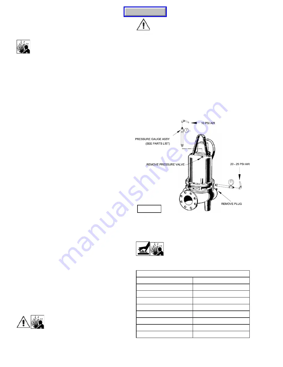
F-1.4) Pressure Test:

Motor Housing- Before checking the pump for leaks around 
the shaft seal, square rings, and cord inlet, the oil level should 
be full as described in section F-1.3. Remove pressure valve 
(5) from motor housing (2). Apply pipe sealant to pressure 
gauge assembly and tighten into pressure valve hole (see 
Fig. 2). Pressurize motor housing to 10 P.S.I. Use a soap 
solution around the sealed areas and inspect joints for “air 
bubbles”. If, after fi ve minutes, the pressure is still holding 
constant, and no “bubbles” are observed, slowly bleed the 
pressure and remove the gauge assembly. Replace the 
Pressure valve using a sealant. If the pressure does not hold, 
then the leak must be located.

Seal Chamber-

 Remove pipe plug (22) from Bearing Bracket 

(21) and check that seal chamber is full of oil. Apply pipe 
sealant to pressure gauge assembly and tighten into hole in 
bearing bracket (21). Pressurize seal chamber to 20-25 PSI 
and check for leaks as outlined above.

CAUTION ! - Pressure builds up extremely 
fast, increase pressure by “TAPPING” air 
nozzle. Too much pressure will damage 
seal. DO NOT exceed 10 P.S.I. in motor 

housing & 20-25  P.S.I. in seal chamber

TABLE 1 - COOLING OIL - Dielectric

SUPPLIER

GRADE

BP

Enerpar SE100

Conoco

Pale Paraffi n 22

Mobile

D.T.E. Oil Light

G & G Oil

Circulating 22

Imperial Oil

Voltesso-35

Shell Canada

Transformer-10

Texaco

Diala-Oil-AX

Woco

Premium 100

FIGURE 2

Manual Index

Summary of Contents for 8DSE-HL Series

Page 1: ...occur As such Crane Pumps Systems reserves the right to change product without prior written noti cation 420 Third Street 83 West Drive Bramton Piqua Ohio 45356 Ontario Canada L6T 2J6 Phone 937 778 89...

Page 2: ...ED VIEW Fig 10 15 PARTS LIST 16 18 RETURNED GOODS POLICY 19 WARRANT 20 START UP REPORT 21 22 WARRANTY REGISTRATION SPECIAL TOOLS AND EQUIPMENT INSULATION TESTER MEGGER DIELECTRIC TESTER SEAL TOOL KIT...

Page 3: ...ngers in pump with power connected Always wear eye protection when working on pumps Make sure lifting handles are securely fastened each time before lifting DO NOT operate pump without safety devices...

Page 4: ...pressure equalized reservoir Material Rotating Faces Carbon Stationary Faces Ceramic Elastomer Buna N Hardware 300 series stainless steel CORD ENTRY 25 Ft 8m Cord Epoxy sealed housing with secondary...

Page 5: ...5 inches mm NOTE PUMP DISCHARGE CAN BE ROTATED IN 45 INCREMENTS Manual Index...

Page 6: ...C 2 Discharge Discharge piping should be as short as possible Both a check valve and a shut off valve are recommended for each pump being used The check valve is used to prevent back ow into the sump...

Page 7: ...st should be performed on the motor The resistance values ohms as well as the voltage volts and current amps should be recorded on the start up report D 3 3 Pump Down Test After the pump has been prop...

Page 8: ...e motor housing to compensate for oil expansion see Fig 9 Set unit upright and ll only until the motor as viewed through the conduit box opening is just covered and no more Reassemble the O ring 11 co...

Page 9: ...ors 12 and 17 The wiring connections should be noted to insure correct connections when reassembling Remove cap screws 19 and hex nuts 20 Vertically lift the outside motor housing 2 from bearing brack...

Page 10: ...HREE PHASE 460 575 VOLT AC THREE PHASE 460 575 VOLT AC Power Cable 10A Power Cable 10A Motor Lead Number Motor Lead Number Green 3 Ground Green Black 1 Red 2 White 3 4 7 Together 5 8 Together 6 9 Toge...

Page 11: ...s in seal plate 25 Check moisture sensor probes 18 for damage Replace by disconnecting wires 16 by removing screws 14 and lockwashers 15 Then remove probe 18 from bearing bracket 21 Seal To expose sha...

Page 12: ...39 into bearing bracket 21 and tighten Fill seal chamber with oil as outlined in paragraph F 1 3 SECTION G REPLACEMENT PARTS G 1 ORDERING REPLACEMENT PARTS When ordering replacement parts ALWAYS furni...

Page 13: ...ler for freedom of operation security and condition Clean impeller and inlet of any obstruction 9 Loosen union slightly to allow trapped air to escape Verify that turn off level of switch is set so th...

Page 14: ...14 FIGURE 9 Manual Index...

Page 15: ...15 FIGURE 10 Manual Index...

Page 16: ...Cable Not Sold Separately 10b 1 052259 Gland Nut 10c 2 052261 Friction Ring 10d 1 052262 Grommet 10e 1 Control Cable Not Sold Separately 10f 1 051448 Gland Nut 10g 1 021531 Friction Ring 10h 1 066871...

Page 17: ...46 Shaft Key 3 8 Sq x 2 1 4 lg Stainless 35 1 102698 Washer 625 x 2 Stainless 36 4 018926 Lockwasher 3 8 Stainless 37 4 084885 Stud 3 8 16 x 4 1 2 lg Steel 38 4 15 23 6 Nut 3 8 16 Zp Steel 39 4 036803...

Page 18: ...1 0000186 Gasket 63 1 105294 Stand 64 1 0082528 Base Elbow 10 65 1 0082530 Hand Hole Cover 66 2 0000479 Capscrew 7 8 9 x 1 50 Lg Stainless 68 1 092871 Gasket Buna S 69 12 002312 Capscrew 7 8 9 x 3 50...

Page 19: ...re That Employees Will Not Be Exposed To Health Hazards In Handling Said Material All Applicable Laws And Regulations Shall Apply IMPORTANT WARRANTY REGISTRATION Your product is covered by the enclose...

Page 20: ...tees in the nature of performance speci cations furnished in addition to the foregoing material and workmanship warranties on a product manufactured by us if any are subject to laboratory tests correc...

Page 21: ...impeller turn freely by hand Yes No Condition of equipment Good Fair Poor Condition of cable jacket Good Fair Poor Resistance of cable jacket Good Fair Poor Resistance of cable and pump motor measured...

Page 22: ...ump Off L1 L2 L2 L3 L3 L1 Voltage supply at panel line connection Pump On L1 L2 L2 L3 L3 L1 Amperage Load connection Pump On L1 L2 L3 FINAL CHECK Is pump seated on discharge properly Check for leaks D...

Page 23: ...STATE ZIP MODEL NO SERIAL NO PART NO BRAND IMPORTANT WARRANTY REGISTRATION Your product is covered by the enclosed Warranty Complete the Warranty Registration Form and return to Crane Pumps Systems In...

Page 24: ...CRANE PUMPS SYSTEMS INC WARRANTY SERVICE GROUP 420 THIRD STREET PIQUA OHIO 45356 U S A FOLD HERE AND TAPE DO NOT STAPLE PLACE STAMP HERE Manual Index...

Reviews: