


8
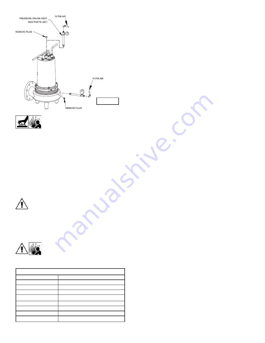
CAUTION! - Pressure builds up extremely
fast, increase pressure by “Tapping” air
nozzle. Too much pressure will damage
seal. DO NOT exceed 10 P.S.I.
Seal Chamber -
Set unit on its side with
fi
ll pipe plug (5)
downward, remove pipe plug (5) and drain all oil from seal
chamber. Apply pipe sealant to pressure gauge assembly
and tighten into hole in bearing bracket (20). Pressurize seal
chamber to 10 P.S.I. and check for leaks as outlined above.
F-1.4) Replacing Oil:
Motor Housing -
Set unit upright and re
fi
ll with new cooling
oil as per Table 1 (see parts list for amount). Fill to just above
motor as an air space must remain in the top of the motor
housing to compensate for oil expansion (see Figure 2 or 12).
Apply pipe thread compound to threads of pipe plug (5) then
assemble to motor housing (2).
IMPORTANT! - For single phase units, oil level
should be below capacitor.
Seal Chamber -
Set unit on its side, with pipe plug (5)
upward, and re
fi
ll with new oil as per Table 1 (see parts list for
amount). Apply pipe thread compound to threads of pipe plug
(5) and assemble to bearing bracket (20).
WARNING! - DO NOT over
fi
ll oil.
Over
fi
lling of motor housing with oil can
create excessive and dangerous hydraulic
pressure which can destroy the pump
and create a hazard. Over
fi
lling oil voids
warranty.
TABLE 1 - COOLING OIL - Dielectric
SUPPLIER
GRADE
Sohio / Standard
SE 40, Energol HL22 or HL32
Shell
Turbo Oil 32
Texaco
Rando HD32, 522
Sun Petroleum
Supar 110, Sunvis 816WR, 911 or 916
Mobile
D.T.E. Oil Light or Rubrex 200
G&G
Circu Oil 22
Allegheny Petroleum
Altrapar 22
Woco
Premium 100
F-2) Impeller and Volute Service:
F-2.1) Disassembly and Inspection:
To clean out volute (25) disconnect power, remove hex nuts
(19), and lock washers (18), vertically lift motor and seal plate
assembly from volute (25). Clean out volute if necessary.
Clean and examine impeller (27), for pitting or wear and
replace if required, inspect square ring (36) and replace if
cut or damaged. If the impeller (27) needs replacing, remove
hex nut (33), and washer (22) . The impeller is keyed onto
the shaft with a square key (32) and to remove, pull impeller
straight off the shaft using a wheel puller, if required. Before
reinstalling, check the motor shaft and impeller bore for
damage.
F-2.2) Reassembly:
To install impeller (27), apply a thin
fi
lm of oil to motor shaft and
slide impeller straight onto shaft, keeping lined up. Drive key
(32) into keyway. Locate washer (22) thread locking compound
to shaft threads, thread hex nut (33) to shaft and torque to 40
ft.-lbs. Rotate impeller to check for binding.
Position square ring (36) on volute
fl
ange and install impeller
and motor housing over studs and onto volute (25). Apply
thread locking compound to threads of each stud (24). Install
lock washers (33) and thread nuts (20) onto stud (23). Torque
30 ft.-lbs. Check for free rotation of motor and impeller.
F-3) Motor and Bearing Service:
F-3.1) Disassembly and Inspection:
To examine or replace the motor (1), capacitor (3, 1 phase
units), and bearing (39), drain oil from motor as outlined
in paragraph F-1.2. Disassemble volute and impeller as
outlined in paragraph F-2.1 and disassemble shaft seal
as outlined in paragraph F-4.1. Position unit upright, using
blocks to avoid resting unit on shaft. Unscrew cable hex bolts
(6) and remove compression
fl
ange (9a) and power cord
(9). Remove snap ring (51) with a
fl
at head screwdriver. Pull
the terminal block (26) out of the motor housing (2) using a
T-bolt or pair of pliers and a .25-20 screw in the threads of
the terminal block (26). Be sure to leave slack on the motor
leads connected underneath. Use needle nose pliers to pull
each female connector off of the pins on the underside of the
terminal block (26) (see Figure 5). The unit voltage should be
noted. Repeat cord and terminal removal procedure for any
sensor cords (10). Remove socket head cap screws (42).
Vertically lift motor housing from bearing bracket by lifting
handle (7). Inspect square rings (36) for damage or cuts.
Remove the motor bolts and lift motor stator from bearing
bracket (20). Disconnect capacitor leads from capacitor (3, 1
phase units). Examine bearing (39) and replace if required.
If replacement is required, remove bearing (39) from motor
shaft using a wheel puller or arbor press. (see Figure 4)
FIGURE 2
Summary of Contents for 3SE3054DS
Page 12: ...12 FIGURE 11 ...
Page 20: ...20 Notes ...


