


11
Seal -
To expose shaft seal (38) for examination, complete
above procedure and slide off outboard rotating member
(38B) (see Figure 7). Remove inboard rotating member
(38D), from shaft. Examine all seal parts and especially
contact faces. Inspect seal for signs of wear such as uneven
wear pattern on stationary members, chips and scratches
on either seal face.
DO NOT
interchange seal components,
replace the entire shaft seal (38).
F-4.2) Reassembly:
Diaphragm- At reassembly, make sure the bulge and molded-
in part number of diaphragm (31) is facing the seal plate
(24). With diaphragm (31) in place, lay diaphragm clamp (37)
in place on seal plate (24) and insert the four cap screws
(43) and lock washers (44) and tighten. Apply pipe thread
compound to moisture sensor electrode (17), if equipped
(or pipe plugs 30), and insert in bearing bracket (20). Attach
wires (15) with screws (13), to the moisture sensor electrodes
(17).
Seal -
Clean and oil seal cavities in bearing bracket (20) and
seal plate (24). Lightly oil
(DO NOT use grease)
outer surface
of inboard stationary member (38E) and outboard stationary
member (38A). Press inboard stationary member (38E)
fi
rmly
into bearing bracket (20) and outboard stationary (38A) into
seal plate (24), using a seal pusher nothing but the seal pusher
is to come in contact with seal face (see Figure 9).
Important ! - DO NOT hammer on the seal pusher-
it will damage the seal face.
Make sure the stationary members are in straight and that the
rubber ring is not out of it’s groove. Slide a bullet over motor shaft.
Lightly oil
(DO NOT use grease)
shaft, bullet and inner surface
of bellows on rotating member (38D) (see Figure 8). With lapped
surface facing bearing bracket (20), slide rotating member (38D)
over bullet and onto shaft, using seal pusher, until lapped faces of
(38D) and (38E) are together (see Figure 8).
Important ! - It is extremely important to keep
seal faces clean during assembly. Dirt particles
lodged between these faces will cause the seal to
leak.
Make sure driving lugs in retainer are matched in rotating
member. Place spring (38C) over shaft and in place on
rotating member (38E), making sure it is seated in retainer
and not cocked or resting on bellows tail. Re-oil shaft and
lightly oil inner surface of outboard rotating member (38B)
With tail section toward bearing bracket (20), slide rotating
member (38B) over bullet onto shaft with seal pusher until
retainer engages spring (38C) and spring is compressed
slightly. Make sure spring (38C) is properly engaged in both
retainers. Insert square ring (36) onto bearing bracket (20).
Slide seal plate (24) over shaft onto bearing bracket (20),
being careful not to damage outboard stationary member
(38A) and align holes for socket head cap screws (35).
Thread socket head cap screws (35) into bearing bracket
(20) and torque to 75 in-lbs. Assemble impeller and volute
per paragraph F-2.2. Fill seal chamber with oil as outlined in
paragraph F-1.4.
SECTION: G REPLACEMENT PARTS
G-1 ORDERING REPLACEMENT PARTS:
When ordering replacement parts, ALWAYS furnish the
following information:
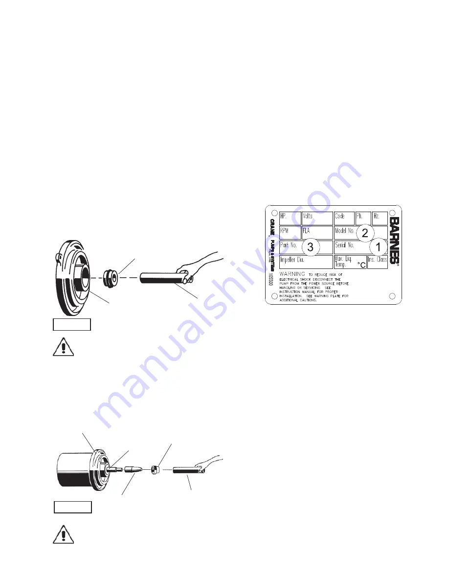
1. Pump serial number and date code. (Paragraph G-4)
2. Pump model number. (Paragraph G-3)
3. Pump part number. (Paragraph G-2)
4. Part description.
5. Item part number.
6. Quantity required.
7. Shipping instructions.
8. Billing Instructions.
G-2 PART NUMBER:
The part number consists of a six (6) digit number, which
appears in the catalog. A one or two letter suf
fi
x may follow this
number to designate the design con
fi
guration. This number is
used for ordering and obtaining information.
G-3 MODEL NUMBER:
This designation consists of numbers and letters which
represent the discharge size, series, horsepower, motor phase
and voltage, speed and pump design. This number is used for
ordering and obtaining information.
G-4 SERIAL NUMBER:
The serial number block will consist of a six digit number,
which is speci
fi
c to each pump and may be preceded by
a alpha character, which indicates the plant location. This
number will also be suf
fi
xed with a four digit number, which
indicates the date the unit was built (Date Code). EXAMPLE:
A012345 0490.
Reference the six digit portion (Serial Number) of this number
when referring to the product.
Rotating Member (38D)
Bullet
Motor & Seal Plate
Seal Pusher
Stationary
FIGURE 10
FIGURE 9
Stationary Member (38A) &
(38E), Polished Face Out
Seal Plate (24) &
Bearing Bracket (20)
Seal Pusher
Summary of Contents for 3SE3054DS
Page 12: ...12 FIGURE 11 ...
Page 20: ...20 Notes ...


