background image

SECTION B: GENERAL INFORMATION

B-1)  To the Purchaser:

Congratulations! You are the owner of one of the finest pumps
on the market today. Barnes

®

 Pumps are products engineered

and manufactured of high quality components. Over one
hundred years of pump building experience along with a
continuing quality assurance program combine to produce a
pump which will stand up to the toughest applications.

This Barnes Pumps, Inc. manual will provide helpful
information concerning installation, maintenance, and proper
service guidelines.

B-2) Receiving:

Upon receiving the pump, it should be inspected for damage
or shortages. If damage has occurred, file a claim immediately
with the company that delivered the pump. If the manual is
removed from the packaging, do not lose or misplace.

B-3) Storage:

Short Term-

 Barnes Pumps are manufactured for efficient

performance following short inoperative periods in storage. For
best results, pumps can be retained in storage, as factory
assembled, in a dry atmosphere with constant temperatures
for up to six (6) months.

Long Term-

 Any length of time exceeding six (6) months, but

not more than twenty-four (24) months. The units should be
stored in a temperature controlled area, a roofed over walled
enclosure that provides protection from the elements (rain,
snow, wind-blown dust, etc.), and whose temperature can be
maintained b40 deg. F and +120 deg. F. If extended
high humidity is expected to be a problem, all exposed parts
should be inspected before storage and all surfaces that have
the paint scratched, damaged, or worn should be recoated with
a water base, air dry enamel paint. All surfaces should then be
sprayed with a rust-inhibiting oil.

Pump should be stored in its original shipping container. On
initial start up, rotate impeller by hand to assure seal and
impeller rotate freely. If it is required that the pump be installed
and tested before the long term storage begins, such
installation will be allowed provided:

1.) The pump is not installed under water for more than

one (1) month.

2.) Immediately upon satisfactory completion of the test,

the pump is removed, thoroughly dried, repacked in the
original shipping container, and placed in a temperature
controlled storage area.

B-4) Service Centers:

For the location of the nearest Barnes Pumps Service Center,
check your Barnes Engineered catalog, your Barnes Pumps,
Inc. representative or Barnes Pumps, Inc. Service Department
in Piqua, Ohio, telephone (937) 778-8947 or Crane Pumps &
Systems Canada, Brampton, Ontario, 
(905) 457-6223.

SECTION C: INSTALLATION

C-1) Location:

These pumping units are self-contained and are recommended
for use in a sump, lift station or basin. The sump, lift station or
basin shall be vented in accordance with local plumbing codes.
This pump is designed to pump sewage, effluent, or other
nonexplosive or noncorrosive wastewater. and shall NOT be
installed in locations classified as hazardous in accordance with
the National Electrical Code (NEC), ANSI/NFPA 70 or the
Canadian Electrical Code (CEC). Never install the pump in a
trench, ditch or hole with a dirt bottom; the legs will sink into the
dirt and the suction will become plugged. 
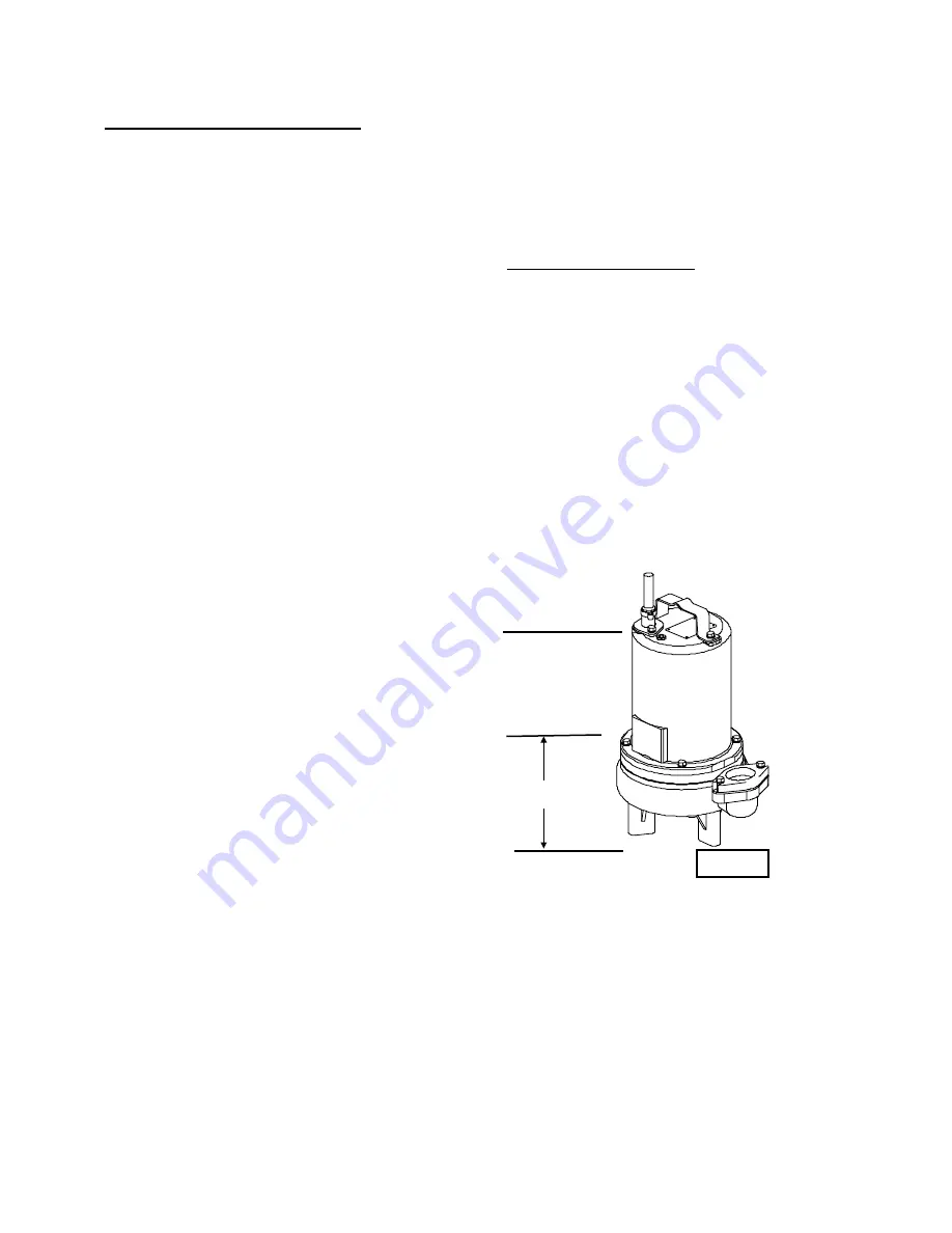
C-1.1) Submergence:

It is recommended that the pump be operated in the submerged
condition and the sump liquid level should never be less than
10 inches above the pump bottom (see Fig. 1). 

C-2) Discharge:

Discharge piping should be as short as possible. Both a check
valve and a shut-off valve are recommended for each pump
being used. The check valve is used to prevent backflow into
the sump. Excessive backflow can cause flooding and/or
damage to the pump. The shut-off valve is used to stop system
flow during pump or check valve servicing.

Barnes Pumps supplies a Stainless Rail Package  for the 2"
models and also a variety of 2" and 3" break-away fitting
discharge systems designed to allow the submersible
wastewater pump to be installed or removed without requiring
personnel to enter the wet well. Contact your local Barnes
Pumps distributor for complete details.

Recommended
Submergence
Level

Fig. 1

10"

Minimum
Submergence
Level

Bottom of Feet

6

Summary of Contents for 2SEV

Page 1: ...such Crane Pumps Systems Inc reserves the right to change product without prior written notification SERIES 2SEV 3SEV L DS 1 5 2 0 HP 3450 RPM Single and Double Seal BARNES 420 Third Street P O Box 6...

Page 2: ...BLE SEAL CROSS SECTION Fig 17 20 DOUBLE SEAL EXPLODED VIEW Fig 18 21 PARTS LIST 22 23 RETURNED GOODS POLICY 25 WARRANTY START UP REPORT WARRANTY REGISTRATION SPECIAL TOOLS AND EQUIPMENT INSULATION TES...

Page 3: ...n and discharge openings DO NOT insert fingers in pump with power connected Always wear eye protection when working on pumps Make sure lifting handles are securely fastened each time before lifting DO...

Page 4: ...0 Volt Custom Molded for Sealing and Strain Relief SPEED 3450 RPM Nominal UPPER BEARING Design Single Row Ball Lubrication Oil Load Radial LOWER BEARING Design Single Row Ball Lubrication Oil Load Rad...

Page 5: ...12 63 321 6 25 159 1 50 38 4 88 124 9 75 248 20 78 528 6 66 169 3SEV L Series 13 99 355 7 06 179 2 06 52 4 88 124 9 75 248 19 07 484 9 03 229 3SEV DS Series 13 99 355 7 06 179 2 06 52 4 88 124 9 75 2...

Page 6: ...d provided 1 The pump is not installed under water for more than one 1 month 2 Immediately upon satisfactory completion of the test the pump is removed thoroughly dried repacked in the original shippi...

Page 7: ...dings become too hot and will automatically reset itself when the pump motor cools to a safe temperature It is recommended that the thermal sensor be connected in series to an alarm device to alert th...

Page 8: ...70 3SEV1522L 1 5 240 1 3450 A 13 5 31 5 12 3 SOW 0 610 2 15 12 49 3SEV1592L 1 5 200 240 3 3450 C 11 5 10 5 27 0 14 4 SOW 0 600 4 22 3SEV1542L 1 5 480 3 3450 F 5 2 13 5 14 4 SOW 0 600 17 0 3SEV1552L 1...

Page 9: ...and refill with new oil as per section F 1 4 SECTION D START UP OPERATION D 1 Check Voltage and Phase Before operating pump compare the voltage and phase information stamped on the pump identificatio...

Page 10: ...emely fast increase pressure by tapping air nozzle Too much pressure will damage seal DO NOT exceed 10 P S I F 1 4 Replacing Oil Motor Housing Set unit upright and refill with new cooling oil as per T...

Page 11: ...ew into volute 1 Torque to 100 in lbs Check for free rotation of motor and impeller F 3 Shaft Seal Service Important Handle seal parts with extreme care DO NOT scratch or mar lapped surfaces F 3 1 Dis...

Page 12: ...d or resting on bellows tail Slide retaining ring 28d over shaft and let rest on spring 28c Replace snap ring 32 in groove of shaft Set square ring 27 in groove on outer seal plate 29 and place outer...

Page 13: ...or winding for shorts and check resistance values Check rotor for wear If rotor or the stator windings are defective the complete motor must be replaced Important All parts must be clean before reasse...

Page 14: ...ads to the underside of the terminal block s 21 54 optional as shown in Figure 13 Note that the pins are numbered underneath the terminal block Place o ring 20 into groove in terminal block and lubric...

Page 15: ...Fig 13 15...

Page 16: ...uration This number is used for ordering and obtaining information G 3 MODEL NUMBER This designation consists of numbers and letters which represent the discharge size series horsepower motor phase an...

Page 17: ...lean impeller cavity and inlet of any obstruction 9 Loosen union slightly to allow trappedair to escape Verify that turn off level of switch is set so that impeller cavity is always flooded Clean vent...

Page 18: ...Fig 15 2SEV L 3SEV L Series Single Seal 18...

Page 19: ...Fig 16 2SEV L 3SEV L Series Single Seal 19...

Page 20: ...Fig 17 2SEV DS 3SEV DS Series Double Seal 20...

Page 21: ...Fig 18 2SEV DS 3SEV DS Series Double Seal 21...

Page 22: ...x 75 Lg Stainless 6 1 129 1 Hex Hd Cap Screw Optional for moisture and temp sensors 12 8 026322 Lockwasher Std 5 16 Stainless 10 026322 Lockwasher Optional for moisture and temp sensors 13 1 103503 Ha...

Page 23: ...Wire Assembly 200 240V 3Ph 50 1 051621 Thermal Sensor Optional for temperature sensor Not Shown 51 2 105155 Wire Assembly Optional for temperature sensor Not Shown 52 2 625 00163 Terminal Connector Op...

Page 24: ...NOTES 24...

Page 25: ...f the warranty contact your local Crane Pumps Systems Inc Distributor RETURNED GOODS RETURN OF MERCHANDISE REQUIRES A RETURNED GOODS AUTHORIZATION CONTACT YOUR LOCAL CRANE PUMPS SYSTEMS INC DISTRIBUTO...

Page 26: ...eld performance Any additional guarantees in the nature of performance specifications must be in writing and such writing must be signed by our authorized representative Due to inaccuracies in field t...

Page 27: ...ottom Does Impeller Turn Freely By Hand YES NO Condition Of Equipment GOOD FAIR POOR Condition Of Cable Jacket GOOD FAIR POOR Resistance of Cable Jacket GOOD FAIR POOR Resistance of Cable and Pump Mot...

Page 28: ...Pump Off L1 L2 L2 L3 L3 L1 Voltage supply at panel line connection Pump On L1 L2 L2 L3 L3 L1 Amperage Load connection Pump On L1 L2 L3 FINAL CHECK Is pump seated on discharge properly Check for leaks...

Page 29: ...ottom Does Impeller Turn Freely By Hand YES NO Condition Of Equipment GOOD FAIR POOR Condition Of Cable Jacket GOOD FAIR POOR Resistance of Cable Jacket GOOD FAIR POOR Resistance of Cable and Pump Mot...

Page 30: ...Pump Off L1 L2 L2 L3 L3 L1 Voltage supply at panel line connection Pump On L1 L2 L2 L3 L3 L1 Amperage Load connection Pump On L1 L2 L3 FINAL CHECK Is pump seated on discharge properly Check for leaks...

Page 31: ...RIAL NO PART NO BRAND FOLD HERE IMPORTANT WARRANTY REGISTRATION Your product is covered by the enclosed Warranty Complete the Warranty Registration Form and returned to Crane Pumps Systems Inc Warrant...

Page 32: ...CRANE PUMPS SYSTEMS INC WARRANTY SERVICE GROUP 420 THIRD STREET P O BOX 603 PIQUA OHIO 45356 0603 U S A PLACE STAMP HERE FOLD HERE AND TAPE DO NOT STAPLE...

Reviews: