background image

5

SECTION B: GENERAL INFORMATION

B-1)  To the Purchaser:
Congratulations!

 You are the owner of one of the fi nest 

pumps on the market today. Barnes® Pumps are products 
engineered and manufactured of high quality components. 
Over one hundred years of pump building experience 
along with a continuing quality assurance program combine 
to produce a pump which will stand up to the toughest 
applications.

This manual will provide helpful information concerning 
installation, maintenance, and proper service guidelines.

B-2) Receiving:

Upon receiving the pump, it should be inspected for 
damage or shortages. If damage has occurred, fi le a claim 
immediately with the company that delivered the pump. If 
the manual is removed from the packaging, do not lose or 
misplace.

B-3) Storage:
Short Term-

 Barnes pumps are manufactured for effi cient 

performance following short inoperative periods in storage. 
For best results, pumps can be retained in storage, as factory 
assembled, in a dry atmosphere with constant temperatures 
for up to six (6) months.

Long Term-

 Any length of time exceeding six (6) months, but 

not more than twenty four (24) months. The units should be 
stored in a temperature controlled area, a roofed over walled 
enclosure that provides protection from the elements (rain, 
snow, wind-blown dust, etc.), and whose temperature can be 
maintained b40 deg. F and +120 deg. F.
If extended high humidity is expected to be a problem, all 
exposed parts should be inspected before storage and all 
surfaces that have the paint scratched, damaged, or worn 
should be recoated with a water base, air dry enamel paint. 
All surfaces should then be sprayed with a rust-inhibiting oil.

Pump should be stored in its original shipping container. On 
initial start up, rotate impeller by hand to assure seal and 
impeller rotate freely.

B-4) Service Centers:

For the location of the nearest Barnes Service Center, check 
your Barnes representative or Crane Pumps & Systems, Inc., 
Service Department in Piqua, Ohio, telephone (937) 778-8947 
or Crane Pumps & Systems Canada, Inc., in Bramton, Ontario 
(905) 457-6223.

SECTION C: INSTALLATION:
C-1) Location:

The pump should be located as near as possible to the liquid 
to be pumped and in no case should the pump be more than 
15 feet above the surface of the liquid supply. The pump 
should always be as level as possible.

C-2) Suction System:

Connect suction pipe or hose to suction inlet. If hose is used, 
it should be of the reinforced type to prevent collapsing under 
suction. Make sure all suction system connections are tight 
and free of air leaks, as even a very slight leak will greatly 
reduce priming ability and pumping effi ciency.

CAUTION! - This pump should not be operated 
without a strainer on the end of the suction line 
to prevent sticks, stones, rags and other foreign 
matter from being drawn into the impeller. The 

strainer should be cleaned regularly to insure full fl ow.

C-3) Discharge System:

Connect discharge hose or pipe to discharge opening in 
pump.

C-4) Lubrication:

The pump requires no lubrication. It is equipped with a 
mechanical shaft seal which is lubricated by the liquid being 
pumped. Lubrication of the engine should be as indicated in 
the Engine Manual.

CAUTION! - DO NOT operate pump without liquid 
in the pump body as operating pump dry will 
result in damage to the seal.

SECTION D: OPERATION:

D-1) Priming:

Start engine; holding governor open for maximum speed will 
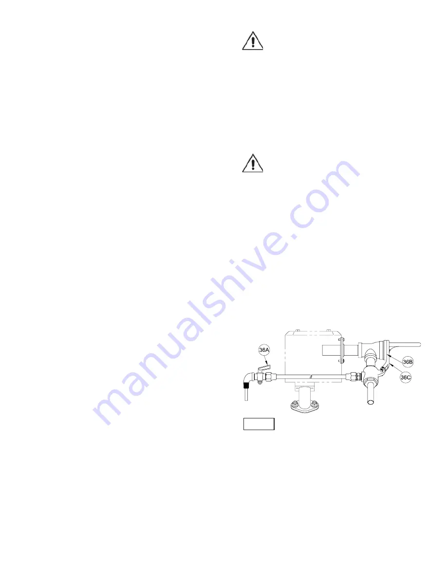
decrease priming time. Open gas cock (36A) in line between 
pump suction and exhaust primer (36), (See Figure 1). With 
exhaust primer handle (36B) and cap (36C), close exhaust 
opening, this diverts engine exhaust gasses through the 
venturi which creates a vacuum in the pump. When a steady 
spray of water is coming from the primer, open the exhaust 
and close the gas cock. (Delay the procedure if spray is 
not full and steady or false prime will result.) Full prime 
can usually be detected by the engine “LOADING UP” as 
pumping action begins.

SECTION E: PUMP SERVICE AND REPAIR:

E-1) Check Valve Service:

Remove cap screws (20) and pull check valve body (19) 
from pump body (14). 

CAUTION:

 Do not pry with sharp 

instrument, but rather bump off with a block of wood and 
a hammer. This will expose the check valve assembly for 
examination or repair.

Examine and replace any part showing wear or damage. 
At reassembly. make sure that the LARGE weight is on the 
CHECK VALVE BODY side of the gasket and that the HINGE 
section of gasket is at TOP.

EXHAUST PRIMER ITEM (36)

Figure 1

Summary of Contents for 2020HC

Page 1: ...s Systems Inc constant product improvement program product changes may occur As such Crane Pumps Systems reserves the right to change product without prior written notification 420 Third Street 83 West Drive Bramton Piqua Ohio 45356 Ontario Canada L6T 2J6 Phone 937 778 8947 Phone 905 457 6223 Fax 937 773 7157 Fax 905 457 2650 www cranepumps com Form No 104613 Rev G Model 2020HC Manual Index ...

Page 2: ...NED GOODS POLICY 11 WARRANT 12 START UP REPORT 13 15 WARRANTY REGISTRATION Other brand and product names are trademarks or registered trademarks of their respective holders Barnes is a registered trademark of Crane Pumps Systems Inc 1998 2002 10 04 4 06 9 06 Alteration Rights Reserved WARNING The engine exhaust from this product contains chemicals know to the State of California to cause cancer bi...

Page 3: ...de DO NOT exceed manufacturers recommendation for maximum performance as this could cause the motor to overheat When towing pump behind a vehicle make sure hitch is properly attached always attach safety chains WARNING If Engine driven never operate in an enclosed building or area where exhaust gases can accumulate Never operate near a building where exhaust gases can seep inside Never operate in ...

Page 4: ...lve Flap Neoprene Weights Cast Iron ASTM A 48 Class 30 BASE Steel with Carring Handles STRAINER 2 51mm Suction Steel PRIMER Exhaust with 0 150 PSI Compound Pressure and Vacuum Gauge ENGINE Make Model Briggs Stratton 245400 Gasoline Type 4 Cycle Single Cylinder Air Cooled Displacement 24 Cu In Oil Capacity 51 Fl Oz Air Cleaner Dual Element Fuel Tank 7 5 Quarts Start Method Recoil Rope Rated Max Dyn...

Page 5: ...ld be located as near as possible to the liquid to be pumped and in no case should the pump be more than 15 feet above the surface of the liquid supply The pump should always be as level as possible C 2 Suction System Connect suction pipe or hose to suction inlet If hose is used it should be of the reinforced type to prevent collapsing under suction Make sure all suction system connections are tig...

Page 6: ...intermediate coupling slide rotating member 9B onto shaft sleeve until lapped faces of 9A and 9B are together If finger pressure is not sufficient use a piece of tubing making sure to press ONLY on bellows tail section not on metal retainer See Figure 2 Make sure driving lugs in retainer are mated in carbon washer Place spring 9C on shaft sleeve and in place on rotating member 9B making sure it is...

Page 7: ...on head higher than pump designed for 4 Insufficient inlet pressure or suction head 5 Clogged foot valve strainer or pump 6 Defective wearplate s 1 Repair or replace suction line 2 Refill reprime pump casing before restarting 3 Lower suction head install foot valve and primer 4 Increase inlet pressure by adding more water to tank or increasing back pressure by turning gate valve on discharge line ...

Page 8: ...8 Figure 3 ...

Page 9: ...16 8 002501 Hex Nut 5 16 18 17 3 015000 Pipe Plug 375 NPT 18 1 021857 Check Valve Assy 18a 1 001338 Weight 2 25 Not Shown 18b 1 001339 Weight 1 56 Not Shown 18c 1 021577 Gasket Not Shown 18d 1 023469 RdHd Screw 1 4 20 x 625 Lg 19 1 021041 Check Valve Body 20 4 1 92 6 Capscrew 5 8 11 x 1 50 Lg 22 1 011113 Gage Compound 0 150 PSI 1 104823 Base Assy 24 1 021924 Base Channel LH 25 1 021925 Base Channe...

Page 10: ...22562 Lock Pin 187 Dia x 875 Lg H 1 2 22009 10 Pan Hd Self Tapping Screw 6 32 Steel I 1 104606 Tee Red 1 00 x 75 x 50 NPT CI J 1 104602 Adapter Assy K 1 011123 Union Half 375 NPT x 1 50 Lg Brass L 2 011124 Flare Nut 625 18 UNC 2B Brass M 1 104617 Tube 375 Dia x 18 Lg Copper N 1 022835 Tube Assy w Elbow 25 NPT O 1 104827 Gasket Graphite P 1 104826 Support Plate Steel Q 4 2 63 1 Rd Hd Screw 8 32 x 5...

Page 11: ...rformance specifications must be in writing and such writing must be signed by our authorized representative Due to inaccuracies in field testing if a conflict arises between the results of field testing conducted by or for user and laboratory tests corrected for field performance the latter shall control RECOMMENDATIONS FOR SPECIAL APPLICATIONS OR THOSE RESULTING FROM SYSTEMS ANALYSES AND EVALUAT...

Page 12: ...ent To Insure That Employees Will Not Be Exposed To Health Hazards In Handling Said Material All Applicable Laws And Regulations Shall Apply IMPORTANT WARRANTY REGISTRATION Your product is covered by the enclosed Warranty To complete the Warranty Registration Form go to http www cranepumps com ProductRegistration If you have a claim under the provision of the warranty contact your local Crane Pump...

Reviews: