background image

Due  to  the  cost  of  energy  or  BHP 
necessary  to  overcome  the  friction 
generated  by  using  a  smaller 
diameter  pipe,  a  larger  diameter 

discharge  pipe  is  commonly  used 
than  the  required  by  the  volute  or 
body.

07

Installation & Operation

In  order  to  determine  the  optimal 
size of the piping, compare the total 
cost  of  the  equipment's  operation 

(cost 

of 

the 

pump, 

control 

equipment,  piping  and  energy 
consumption).  By  increasing  the 
discharge  diameter  reasonably,  it 

reduces the required BHP due to the 
low  friction.  Perform  different  tests 
using  several  piping  diameters  until 
you find the more convenient.

The  pipe,  valves,  etc.  should  be 
perfectly  align  with  the  volutes 
suction  and  discharge  centerlines, 

this  to  avoid  any  excessive  loads  on 

the  pumps  volute.  If  needed,  install 
new  expansive  joints  to  protect  the 
pump  from  excessive  thermal  or 

pressure forces.

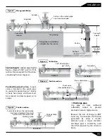
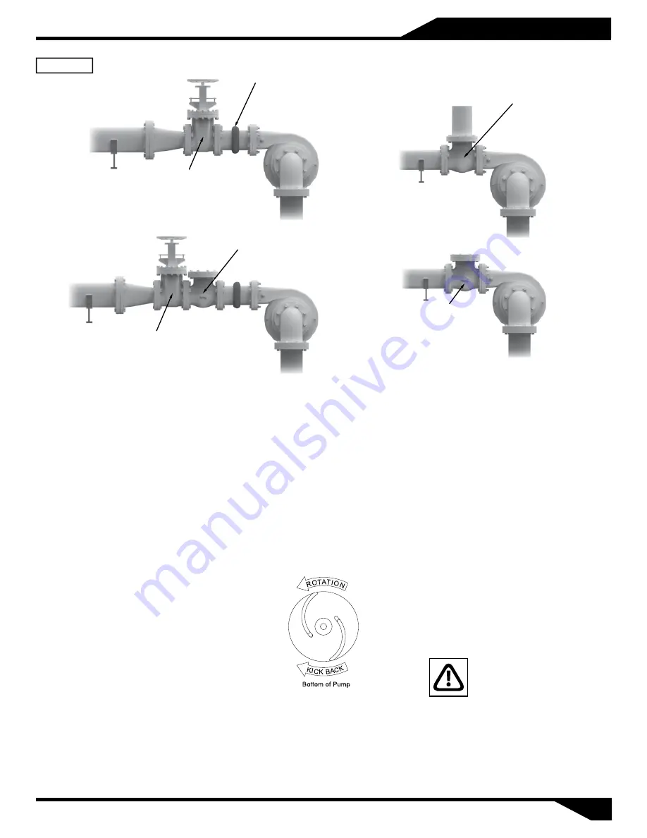
Safety shutoff

valve

Swing check valve

could cause a

“water hammer”

Expansive

joint

Service valve.

Service valve

Retarded action

check valve

INCORRECT

CORRECT

Figure 6

Discharge piping.

Install  the  foot  valve  at  the  suction 

pipe (Figure 1) and fill with liquid the 
superior  part  of  the  pump´s  body. 
Sometimes  air  is  trapped  inside  the 
body, to remove it you should uncap 

the  male  plug  until  the  liquids  spills 
out. Re-install  the  male  plug  using  a 
sealant.

IMPORTANT!  -  Do  not 
operate  pump  without  
priming first. Operating dry 
will damage seal. 

Pre-Operation

1.

   C

heck  Voltage  and  Phase  - 

Compare  the  voltage  and  phase 

information  stamped  on  the 
pump name plate.

2.

   Check 

Pump Rotation -

 Improper 

motor rotation can result in poor 
pump  performance  and  can 
damage  the motor and/or  pump. 
Check  rotation  on  three  phase 

units  by  momentarily  applying 
power and observe the "kickback". 

4.

   P

riming -

 Every centrifugal pump 

must  be  primed  (suction  pipe  and 
pump´s  body  should  have  liquid), 
before operating.

Kickback  should  always  be  in  a 

counter-clockwise 

direction 

as 

viewed  from  motor  end  or  opposite 

to impeller rotation. Impeller rotation 
is  counter-clockwise  as  viewed  from 

bottom of pump.

3.

   N

ame  Plate  - 

Record  the 

information  from  the  pump  name 

plate  to  drawing  in  front  of  manual 
for future reference.

barmesapumps.com

Summary of Contents for IA1-2-4

Page 1: ...Installation Operation Maintenance Manual End Suction Centrifugal Pumps IA 2 125 HP 1750 3500 RPM IMPORTANT Read all instructions in this manual before operating or servicing a pump barmesapumps com...

Page 2: ...cing the pump or any accessory items associated with or near the pump Do not block or restrict the discharge pipe hose T h i s p u m p i s n o t i n t e n d e d f o r u s e i n swimming pools or water...

Page 3: ...ally balanced SEAL Mechanical type 01 Ceramic stationary part carbon ring seal and exclusion in the rotatingpart Buna Nelastomerandstainlesssteelspring SHAFTSLEEVE Stainlesssteel O RINGS Buna N MOTOR...

Page 4: ...xidant liquid Installation The pump should be as close as possible to the liquid to be pumped with a minimum number of couplings adapters etc in order to reduce friction on the suction side The suctio...

Page 5: ...1 21 9 7 28 1 86 0 6 180 757 66 3 26 7 8 9 2 27 0 73 0 3 200 833 80 32 2 10 07 2 72 0 87 0 35 220 908 95 38 1 12 6 3 21 1 03 0 41 240 984 111 44 5 14 7 3 74 1 2 0 48 260 1060 128 51 3 16 9 4 3 1 38 0...

Page 6: ...3 36 STANDARD 45 ELBOW 0 38 0 54 0 61 0 77 0 92 1 15 1 53 1 83 2 29 STANDARD TEE 1 68 2 29 2 75 3 36 4 28 5 19 6 71 8 23 10 1 ANGLE GLOBE VALVE OPEN 3 97 5 49 6 71 8 23 10 7 12 2 16 8 21 3 25 9 GLOBE...

Page 7: ...e must be removed to allow trapped air to escape 0 39 of inclination per 3 28 ft CORRECT INCORRECT Air pocket Figure 3 Inclination Check valve completely open CORRECT D 6x D min Pressurized water Figu...

Page 8: ...tion check valve INCORRECT CORRECT Figure 6 Discharge piping Install the foot valve at the suction pipe Figure 1 and fill with liquid the superior part of the pump s body Sometimes air is trapped insi...

Page 9: ...tighten the nuts until the dripping decreases but not cease Frame All pumps come with factory lubricated bearings It is very important to have oil in the oil tank Use oil DTE26 Change the oil every 1...

Page 10: ...al type pumps generally use 2 different types of flexible couplings the Lovejoy type with rubber spider and the Steelflex type F with grids buffer The first mentioned coupling requires no lubrication...

Page 11: ...ance between the hubs and rest it on any of the covers Lubricate the slots and clearance with as much grease as possible Fill the spaces between the grid and around it with grease Remove excess Oil th...

Page 12: ...005 0 156 4 1 8 0 028 0 005 0 02 0 007 0 188 5 1 8 0 033 0 005 0 02 0 007 0 188 6 1 8 0 038 0 005 0 02 0 007 0 188 7 1 8 0 045 0 005 0 02 0 007 0 188 8 1 8 0 052 0 01 0 03 0 01 0 25 9 1 8 0 057 0 01 0...

Page 13: ...5 3 63 11 81 IA1 7 5 2 7 5 3515 3 213JM 13 25 IA1 10 2 10 3505 3 215JM 7 14 75 IA1 15 2 15 3530 3 254JM 8 25 19 06 IA1 20 2 20 3525 3 256JM 10 19 65 IA1 H 3 4 3 1740 3 182JM 4 5 6 88 7 5 4 5 3 63 11 8...

Page 14: ...525 3 284JM 7 11 75 11 9 5 4 75 20 5 4 5 6 88 7 5 3 63 11 81 0 41 6 25 10 10 4 5 0 53 MODEL HP RPM PHASE FRAME A B C D E F G H IA2 2 4 2 1735 3 145JM 3 5 6 88 5 5 5 2 75 12 4 03 0 34 IA2 10 2 10 3505...

Page 15: ...NCL ODP 4 HOLES HIGH PRESSURE CENTRIFUGAL PUMP MODEL IA3 IA3H GENERAL DIMENSIONS MODEL HP RPM PHASE FRAME A B C D E F G H IA3 3 4 3 1740 3 182JM 4 5 IA3 5 4 5 1730 3 184JM IA3 7 5 4 7 5 1750 3 213JM 5...

Page 16: ...DEL HP RPM PHASE FRAME A B C D E F G IA4 40 2 40 3530 3 324TSC 24 10 5 IA4 50 2 50 3530 3 326TSC 25 5 12 IA4 60 2 60 3565 3 364TSC 28 11 25 IA4 75 2 75 3555 3 365TSC 29 12 25 IA4 100 2 100 3560 3 405T...

Page 17: ...IMPELLER IA1 5 2 6 81 03140031B IMPELLER IA1 2 4 IA1 7 5 2 7 50 03140031C 5 1 SHAFT SLEEVE 30400808 6 1 SLINGER 92010014 7 1 MECHANICAL SEAL 31030131 8 1 O RING 92010033 9 1 IMPELLER S SCREW 91010345C...

Page 18: ...10 1 11 1 12 1 ITEM QTY DESCRIPTION PART ELECTRIC MOTOR 200 230 460 ODP 3 HP 1740 RPM 3 PH FRAME 182T JM 15 HP 3530 RPM 3 PH FRAME 254T JM 20 HP 3525 RPM 3 PH FRAME 256T JM 25 HP 3530 RPM 3 PH FRAME 2...

Page 19: ...R S SCREW FOR 15 TO 40 HP 91010351 LOCK WASHER 3 8 SS FOR 3 TO 10 HP 91010061 LOCK WASHER 1 2 SS FOR 15 TO 40 HP 91010062 IMPELLER WASHER FOR 3 TO 10 HP 30400418 IMPELLER WASHER FOR 15 TO 40 HP 304004...

Page 20: ...30400418 IMPELLER WASHER FOR 15 TO 50 HP 30400416 SHAFT KEY FOR 3 HP TO 7 5 HP 30400631 SHAFT KEY FOR 15 TO 50 HP 30400633 13 8 STUD 3 8 16X 1 50 91010303 14 8 HEX NUT 3 8 91010413 15 8 LOCK WASHER 3...

Page 21: ...MPELLER IA1 XH 3 4 9 19 IMPELLER IA1 XH 5 4 9 19 5 1 SHAFT SLEEVE FOR 3 TO 25 HP 30400829 6 1 SLINGER FOR 3 TO 25 HP 92010016 7 1 MECH SEAL FOR 3 TO 25 HP 31030133 8 1 O RING 92010033 9 1 IMPELLER S S...

Page 22: ...pacity is not too much The pump is operating in the range of NPSHR If reducing ow makes the noise gone then the problem is in the point above partially close the discharge valve The bearings for wear...

Page 23: ......

Page 24: ......

Reviews: