background image

Manual 2100-365Q
Page

26 of 73

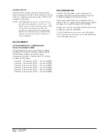
NATURAL GAS INPUT RATE

Natural gas heating value (BTU/cu. ft.) can vary
significantly.  Before starting natural gas input check,
obtain gas heating value at your location from local
supplier.  You will need a stopwatch to measure actual
gas input.

1. Gas supply pressure must be between 5 and 7 inches

W.C. for natural gas.

2. Turn off all other gas appliances.  You may leave

pilots on.

3. Start furnace following “Operating Instructions” on

front door.

4. Let furnace warm up for 6 minutes.

5. Locate gas meter.  Determine which dial has the

least cubic feet of gas and how many cubic feet per
revolution it represents.  This is usually one-half, one
or two cubic feet per revolution.

6. With stopwatch, measure time it takes to consume

two cubic feet of gas.

If dial is one-half cubic foot per revolution,
measure time for four revolutions.

If dial is one cubic foot per revolution, measure
time for two revolutions.

If dial is two cubic feet per revolution, measure
time for one revolution.

7. Divide this time by two.  This gives average time for

one cubic foot of gas to flow through meter.
Example:  If it took 58 seconds for two cubic feet to
flow, it would take 29 seconds for one cubic foot to
flow.

8. Calculate gas input using this formula:

Gas Heating Value (BTU/cu. ft.)
         x 3,600 sec/hr

  Gas input =

= BTU/hour

   Time (Seconds for one

              cubic foot of gas)

Example:

Assume it took 29 seconds for one cubic foot of gas
to flow and heating value of 1,000 BTU/cu. ft.

    1,000 x 3,600

 Gas input =

=

 124,138 

BTU

                                          29

If you left no other pilots on, this is the furnace gas
input.

PROPANE (LP) GAS INPUT RATE

1. Make sure you have proper main burner orifices.

2. Gas supply pressure must be between 11 and 13

inches W.C. for propane (LP) gas.

3. Start furnace following “Operating Instructions” on

front door.

4. Let furnace warm up for 6 minutes.

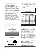
5. Adjust manifold pressure to 10.0 W.C. ± 0.3 inches

W.C.  See Section 19, “Manifold Pressure
Adjustment”.

          WARNING

Propane (LP) gas installations do not have
gas meters to double check input rate.
Measure manifold pressure adjustment with
an accurate manometer.  Failure to accurately
adjust pressure could cause heat exchanger
failure, asphyxiation, fire or explosion,
resulting in damage, injury or death.

          WARNING

Do not set Propane (LP) manifold pressure at
11.0 inches W.C.  It could cause heat
exchanger failure.

9. If you left water heater, dryer or range pilots on,

allow for them in calculating correct furnace gas
input.  A quick way is to allow 1,000 BTU per hour
for a water heater, 500 BTU per hour for dryer and
500 BTU per hour for each range burner pilot.

Example:

If you left gas water heater, dryer, two range burner
pilots and one oven pilot on, allow:

Water heater pilot

1,000 BTU per hour

Dryer pilot

500 BTU per hour

2 range burner pilots

1,000 BTU per hour

1 range oven pilot

500 BTU per hour

3,000 BTU per hour

Subtracting 3,000 BTU per hour from 124,138 BTU
per hour measured above equals 121,138 BTU per
hour.  This would be the correct furnace gas input
after allowing for pilots left on.

10. Manifold pressure may be adjusted within the range

of 3.2 inches W.C. to 3.8 inches W.C. to get rated
input ± 2 percent.  See Section 19, “Manifold
Pressure Adjustment”.  If you cannot get rated input
with manifold pressure within the allowable range,
you must change orifices.

Summary of Contents for WG242-A

Page 1: ...facturing Company Inc Bryan Ohio 43506 Since 1914 Moving ahead just as planned Copyright 2004 WARNING READ ALL INSTRUCTIONS CAREFULLY BEFORE BEGINNING THE INSTALLATION THE INSTALLATION MUST COMPLY WIT...

Page 2: ...7 Thermostats 21 18 Gas Supply Piping 24 19 Manifold Pressure Adjustment 25 20 Checking Gas Input Rate 25 26 21 Standard Orifice Sizing High Altitude Derate 27 22 Conversion of Gas Input BTUH From Hig...

Page 3: ...f Operation Electronic Blower Control 36 Figure 18 Furnace Control Board Blower Control 37 Figure 19 Fan Blade 46 Figure 20 Low NOx Insert 46 TABLES Table 1 Specifications WG24 36 Models 7 Table 1A Sp...

Page 4: ...47 4044 COPYRIGHT SEPTEMBER 2003 BARD MANUFACTURING COMPANY INC BRYAN OHIO 43506 USA Manufactured under the following U S patent numbers 5 485 878 5 002 116 4 924 934 4 875 520 4 4825 936 These public...

Page 5: ...l a i c r e m m o C P 3 P V R C G W 5 P V R C G W g n i t a l u d o M y l l u F r e z i m o n o c E 1 E 3 M F I E G W 5 M F I E G W t l o V 0 3 2 r o t a l i t n e V y r e v o c e R y g r e n E R 3 A...

Page 6: ...dure and any tags and or labels attached to the equipment All duct work supply and return must be properly sized for the design airflow requirement of the equipment Air Conditioning Contractors of Ame...

Page 7: ...8 0 2 0 3 2 0 6 4 s p m A d a o L d e t a R 5 0 1 5 9 6 6 2 6 3 3 5 3 1 5 2 1 5 9 0 9 5 6 1 4 1 0 1 5 9 5 t n e r r u C n o i t c e l e S t i u c r i C h c n a r B 5 0 1 7 6 5 3 1 4 1 5 9 5 6 1 0 1 5...

Page 8: ...2 0 3 2 0 6 4 s p m A d a o L d e t a R 5 9 1 1 2 5 4 1 5 3 1 8 5 1 2 1 2 3 1 5 2 1 2 6 0 3 7 2 5 9 1 7 1 9 t n e r r u C n o i t c e l e S t i u c r i C h c n a r B 1 2 5 1 6 7 2 2 3 1 4 6 0 3 5 9 1...

Page 9: ...N AIR EXHAUST COMBUSTION AIR INTAKE CONTROL LOW VOLTAGE ENTRANCES CIRCUIT BREAKER VENT OPTION MIS 2123 A UNIT A B C D E F G H I J K L M N O W G 24 W G 30 W G 3 6 7 88 27 88 13 88 24 25 40 25 63 81 63...

Page 10: ...nd in the absence of specific recommendations from the local authority having jurisdiction equipment ratings shall be reduced as specified in Section 21 5 TRANSPORTATION DAMAGE All units are packed se...

Page 11: ...ible wall use a minimum of Figure 1 A dimension plus 2 inches and B dimension plus 2 inches See Figures 4 and 5 for details 3 Locate and mark lag bolt locations and bottom mounting bracket location 4...

Page 12: ...PTIONAL 12 FLANGE SCREWS UNIT SUPPORT 1 MIN NECCESSARY NO CLEARANCE SUPPLY AIR DUCT RETURN AIR DUCT CONTROL PANEL VESTIBULE DOOR WALL STRUCTURE OUTSIDE 1 CLEARANCE ON ALL FOUR SIDES OF SUPPLY AIR DUCT...

Page 13: ...Manual 2100 365Q Page 13 of 73 FIGURE 2A MOUNTING INSTRUCTIONS FOR WG42 WG48 AND WG60...

Page 14: ...of one 1 inch clearance must be maintained between the supply air duct and combustible materials This is required for the first three 3 feet of ducting It is important to insure that the one 1 inch m...

Page 15: ...Manual 2100 365Q Page 15 of 73 FIGURE 4 WALL MOUNTING INSTRUCTIONS FIGURE 5 WALL MOUNTING INSTRUCTIONS...

Page 16: ...Manual 2100 365Q Page 16 of 73 FIGURE 6 COMMON WALL MOUNTING INSTALLATIONS...

Page 17: ...ed air from the condenser to recirculate to the condenser inlet TABLE 2 MINIMUM INSTALLATION CLEARANCES s l a i r e t a m e l b i t s u b m o c m o r f t c u D t e l t u O t e e f 3 t s r i f h c n i...

Page 18: ...ang The kit includes a stainless steel transition drain tee silicone sealant and drain tubing If unit is installed with vertical vent kit annually inspect the vent system and drain Replace any portion...

Page 19: ...nce spillage at the draft hood relief opening after 5 minutes of main burner operation Use the flame of a match or candle 6 After it has been determined that each appliance connected to the venting sy...

Page 20: ...r electrical ground could result in electric shock or fire 15 WIRING MAIN POWER Refer to unit rating plate for wire sizing information and maximum fuse or HACR type circuit breaker size Each outdoor u...

Page 21: ...All models are equipped with single primary voltage transformers and no rewiring is required TABLE 3 THERMOSTAT WIRE SIZE r e m r o f s n a r T A V A L F e g u a G e r i W m u m i x a M e c n a t s i...

Page 22: ...Manual 2100 365Q Page 22 of 73 FIGURE 11 LOW VOLTAGE WIRING...

Page 23: ...Manual 2100 365Q Page 23 of 73 FIGURE 12 GAS PIPE CONNECTION...

Page 24: ...0 0 0 0 5 0 5 0 0 0 6 5 0 0 0 5 1 1 0 0 0 5 1 2 0 0 0 0 4 4 0 6 0 0 0 0 5 0 0 0 5 0 1 0 0 0 5 9 1 0 0 0 0 0 4 0 7 0 0 0 6 4 0 0 0 6 9 0 0 0 0 8 1 0 0 0 0 7 3 0 8 0 0 0 3 4 0 0 0 0 9 0 0 0 0 7 1 0 0 0...

Page 25: ...kits may be purchased from your local distributor 5 Slowly open equipment shut off valve in gas supply line just ahead of furnace Start furnace following Operating Instructions on front door 6 Slowly...

Page 26: ...the furnace gas input PROPANE LP GAS INPUT RATE 1 Make sure you have proper main burner orifices 2 Gas supply pressure must be between 11 and 13 inches W C for propane LP gas 3 Start furnace followin...

Page 27: ...5 7 0 6 0 0 5 7 6 6 0 8 8 5 0 4 3 5 6 2 6 8 6 5 0 8 1 3 6 8 1 9 4 5 0 2 0 1 6 0 6 4 3 5 0 0 4 9 5 8 8 4 2 5 0 2 3 8 5 3 7 2 1 5 0 7 9 6 5 4 4 5 0 5 0 6 1 6 5 2 7 5 9 4 0 8 0 5 5 5 6 9 8 4 5 0 4 4 5 4...

Page 28: ...F 0 0 0 0 1 o t 1 0 0 8 h c t i w S e r u s s e r P s e r i u q e R e g n a h C e c i f i r O d n a e g n a h C t n e t n o C U T B n o d e s a B U T B 0 5 2 0 2 r e n r u B r e P 9 4 7 0 0 7 0 6 2 0...

Page 29: ...r e d 0 1 l a n o i t p o l a n o i t p O d l e i F 0 1 d e t r e v n o C e t a r e D t a e H s a G e u l a V t F u C U T B o N t e e F 0 0 0 6 o t p U t p e c x E s e g n a h C t n e t n o C U T B r...

Page 30: ...oximately 2 feet from furnace Locate thermometer tip in center of plenum to insure proper temperature measurement 6 Place second thermometer in return air duct approximately 2 feet from furnace Locate...

Page 31: ...ontactor will de energize immediately The lockout timer will go into a soft lockout and stay in soft lockout until the high pressure switch closes and the delay on make time has expired If the high pr...

Page 32: ...e DOM timing on power up and after power interruptions is equal to 2 minutes plus 10 of Delay on Break DOB setting 0 5 minute 30 seconds DOB 123 second DOM 1 0 minute 60 seconds DOB 126 second DOM 2 0...

Page 33: ...Manual 2100 365Q Page 33 of 73 26 LIGHTING AND SHUTDOWN INSTRUCTIONS FIGURE 15 INSTRUCTION LABEL...

Page 34: ...ht on small mirror or an extension handle Remove the screws securing the inducer and collector box Now inspect the upper tubes of the heat exchanger Check the exterior of the heat exchanger and the in...

Page 35: ...sure the supply and return air flange sleeves or duct work are securely fastened to unit and physically sound d Supply and return grilles must be open and free from obstructions e Inspect to make sur...

Page 36: ...cle on and off until the condensing pressure remains above 180 PSIG LAC energizes the fan motor at 280 PSIG de energizes at 180 PSIG FIGURE 17 SEQUENCE OF OPERATION ELECTRONIC BLOWER CONTROL N O I T C...

Page 37: ...f it is desirable to have both HEAT COOL blower motor speed at the same speed install a jumper wire between HEAT and COOL terminals of the integrated furnace control board and place both unused motor...

Page 38: ...0 7 0 2 1 1 0 2 1 1 0 4 9 4 0 0 9 7 0 3 0 1 0 3 0 1 0 6 8 5 0 0 1 9 0 1 7 0 5 9 6 0 0 0 8 0 4 8 P S E s e h c n I H2 O E D O M G N I L O O C E D O M G N I T A E H d n a N A F L A U N A M l i o C t e W...

Page 39: ...3 0 1 0 9 1 1 0 3 0 1 0 6 8 5 0 0 5 0 1 0 1 9 0 9 0 1 0 5 9 0 9 0 1 0 5 9 6 0 0 4 9 0 8 9 0 8 9 0 4 8 P S E s e h c n I H2 O E D O M G N I L O O C E D O M G N I T A E H d n a N A F L A U N A M l i o C...

Page 40: ...1 0 3 0 1 0 9 1 1 0 3 0 1 0 6 8 5 0 0 5 0 1 0 9 0 1 0 5 9 0 9 0 1 0 5 9 6 0 0 4 9 0 8 9 0 8 9 0 4 8 P S E s e h c n I H2 O E D O M G N I L O O C E D O M G N I T A E H d n a N A F L A U N A M l i o C...

Page 41: ...3 1 1 0 3 4 1 0 3 1 1 P S E s e h c n I Hs O E D O M G N I L O O C N A F L A U N A M d n a E D O M G N I T A E H l i o C t e W U T B 0 0 0 0 0 1 t u p n I U T B 0 0 0 0 9 h g i H m u i d e M w o L h g...

Page 42: ...0 4 3 1 0 3 4 1 0 3 4 1 0 3 1 1 P S E s e h c n I Hs O E D O M G N I L O O C N A F L A U N A M d n a E D O M G N I T A E H l i o C t e W U T B 0 0 0 0 0 1 t u p n I U T B 0 0 0 0 9 h g i H m u i d e...

Page 43: ...3 1 0 3 4 1 0 3 4 1 0 3 1 1 P S E s e h c n I Hs O E D O M G N I L O O C N A F L A U N A M d n a E D O M G N I T A E H l i o C t e W U T B 0 0 0 0 0 1 t u p n I U T B 0 0 0 0 9 h g i H m u i d e M w...

Page 44: ...c e l e s e h t r o f e t a r e p o l l i w r e w o l b r i a t r o f m o c e h t e t a r e p o o t e u n i t n o c l l i w r e w o l b r i a t r o f m o c e h t n o i t a r e p o S T I N U Y T E F A...

Page 45: ...8 6 2 3 2 8 6 4 3 3 8 6 6 3 B D g e d 0 8 B W g e d 7 6 e d i S w o L e d i S h g i H 7 7 8 2 2 9 7 5 4 2 1 8 2 6 2 2 8 9 7 2 4 8 8 9 2 5 8 6 1 3 7 8 5 3 3 8 8 5 5 3 9 8 5 7 3 B D g e d 5 8 B W g e d...

Page 46: ...9 FAN BLADE 36 LOW NOX BURNER ASSEMBLY N SUFFIX MODELS ONLY U S INSTALLATIONS ONLY NATURAL GAS MODELS ONLY Model numbers designated with an N are designed for low NOx emissions which comply with all C...

Page 47: ...7 5 C 3 0 3 G W 3 4 3 5 8 0 4 8 5 A 4 4 3 5 8 0 4 9 5 A 2 6 3 G W A 8 3 1 5 8 0 4 0 6 A 5 3 1 5 8 0 4 9 4 B 2 6 3 G W A 8 3 2 5 8 0 4 1 6 A 5 3 2 5 8 0 4 1 5 C 3 6 3 G W 5 4 3 5 8 0 4 2 6 A 6 4 3 5 8...

Page 48: ...Manual 2100 365Q Page 48 of 73 WG242 A 230 208 60 1...

Page 49: ...Manual 2100 365Q Page 49 of 73 WG242 A WG362 A 230 208 60 1...

Page 50: ...Manual 2100 365Q Page 50 of 73 WG242 B 230 208 60 3...

Page 51: ...Manual 2100 365Q Page 51 of 73 WG242 B WG362 B 230 208 60 3...

Page 52: ...Manual 2100 365Q Page 52 of 73 WG243 C 460 60 3...

Page 53: ...Manual 2100 365Q Page 53 of 73 WG243 C 460 60 3...

Page 54: ...Manual 2100 365Q Page 54 of 73 WG302 A 230 208 60 1...

Page 55: ...Manual 2100 365Q Page 55 of 73 WG302 A WG482 A WG602 A 230 208 60 1...

Page 56: ...Manual 2100 365Q Page 56 of 73 WG302 B 230 208 60 3...

Page 57: ...Manual 2100 365Q Page 57 of 73 WG302 B WG482 B WG602 B 230 208 60 3...

Page 58: ...Manual 2100 365Q Page 58 of 73 WG303 C 460 60 3...

Page 59: ...Manual 2100 365Q Page 59 of 73 WG303 C 460 60 3...

Page 60: ...Manual 2100 365Q Page 60 of 73 WG362 A 230 208 60 1...

Page 61: ...Manual 2100 365Q Page 61 of 73 WG362 B 230 208 60 3...

Page 62: ...Manual 2100 365Q Page 62 of 73 WG363 C 460 60 3...

Page 63: ...Manual 2100 365Q Page 63 of 73 WG363 C 460 60 3...

Page 64: ...Manual 2100 365Q Page 64 of 73 WG423 A 230 208 60 1...

Page 65: ...Manual 2100 365Q Page 65 of 73 WG423 A 230 208 60 1...

Page 66: ...Manual 2100 365Q Page 66 of 73 WG423 B 230 208 60 3...

Page 67: ...Manual 2100 365Q Page 67 of 73 WG423 B 230 208 60 3...

Page 68: ...Manual 2100 365Q Page 68 of 73 WG424 C 460 60 3...

Page 69: ...Manual 2100 365Q Page 69 of 73 WG424 C 460 60 3...

Page 70: ...Manual 2100 365Q Page 70 of 73 WG482 A WG602 A 230 208 60 1...

Page 71: ...Manual 2100 365Q Page 71 of 73 WG482 B WG602 B 230 208 60 3...

Page 72: ...Manual 2100 365Q Page 72 of 73 WG483 C WG603 C 460 60 3...

Page 73: ...Manual 2100 365Q Page 73 of 73 WG483C WG603 C 460 60 3...

Reviews: