Bard WA7013B, Installation Instructions Manual
Looking for the Installation Instructions Manual for the Bard WA7013B? Look no further! You can download the manual for free from manualshive.com. This user-friendly manual will guide you through the installation process step by step, ensuring a smooth set-up for your Bard WA7013B.
Share
Download


Reviews:
No comments
Related manuals for WA7013B

Duct Type Series
Brand: Samsung Pages: 40

BFK1901R
Brand: Saneo Pages: 49

DD 430
Brand: Valeo Pages: 60

GMV-ND07PLS-T
Brand: AC Pro Pages: 28

HCF RTL G 17
Brand: Lennox Pages: 5

Precedent WSC072E
Brand: Ingersoll-Rand Pages: 68

FVA71AMVEB
Brand: Daikin Pages: 36

ACDC12B
Brand: hotspot energy Pages: 27

EH1924
Brand: Prem-I-Air Pages: 12

AS 500 HEPA
Brand: Hawk Pages: 2

Aquaria
Brand: Olimpia splendid Pages: 44

ASH218JCDDA
Brand: GE Pages: 80

ASH12AL
Brand: GE Pages: 40

AW CGHLAWKNTC Series
Brand: Samsung Pages: 24

SCDF Series
Brand: Technibel Pages: 16

51500
Brand: Honeywell Pages: 7
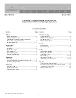
AE8-1384 R6
Brand: Emerson Pages: 19

Air Conditioners
Brand: Motorola Pages: 36


