Manual No.: 2100-200K
Supersedes: 2100-200J
File:
Volume
III
, Tab 16
Date:
04-19-99
Bard Manufacturing Company
Bryan, Ohio 43506
Since 1914...Moving ahead, just as
planned.
© Copyright 1999
MIS-656
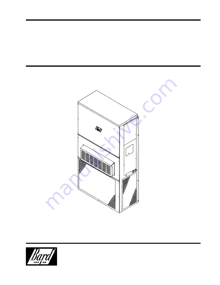
Models:
WA181, WA241
Wall Mounted
Packaged Air Conditioner
Installation
Instructions


