


Manual 2100-344
Page
11
COMPRESSOR CUTOFF THERMOSTAT
WIRING (15 KW ONLY)
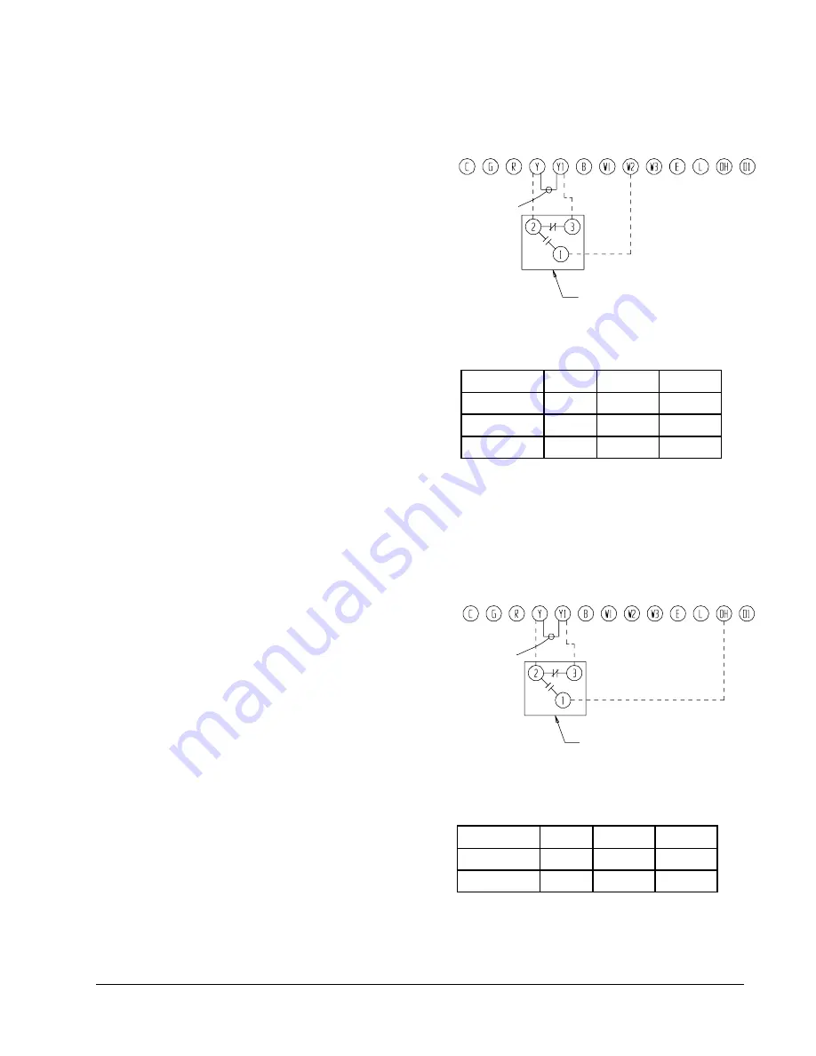
FIGURE 9
UNIT 24V TERMINAL BOARD
MIS-1188
FIGURE 10
UNIT 24V TERMINAL BOARD
MIS-1189
TABLE 8
5 and 10 KW
l
e
d
o
M
W
K
s
t
l
o
V
e
s
a
h
P
4
2
2
1
H
P
0
1
,
5
,
0
0
3
2
1
0
3
2
1
H
P
0
1
,
5
,
0
0
3
2
1
6
3
2
1
H
P
0
1
,
5
,
0
0
3
2
1
TABLE 9
15 KW ONLY
l
e
d
o
M
W
K
s
t
l
o
V
e
s
a
h
P
0
3
2
1
H
P
5
1
0
3
2
1
6
3
2
1
H
P
5
1
0
3
2
1
COMPRESSOR CUTOFF THERMOSTAT
WIRING (5 and 10 KW)
COMPRESSOR CUTOFF THERMOSTAT
and OUTDOOR THERMOSTAT WIRING
Heat pump compressor operation at outdoor temperatures
below 0° F are neither desirable nor advantageous in terms
of efficiency. Since most equipment at time of manufacture
is not designated for any specific destination of the county
and most of the equipment is installed in areas not
approaching the lower outdoor temperature range, the
compressor cutoffs are not factory installed.
Outdoor thermostats are available to hold off various banks
of electric heat until needed as determined by outdoor
temperature. The set point of either type of thermostat is
variable with geographic region and sizing of the heating
equipment to the structure. Utilization of the Heating
Application Data and the heat loss calculation of the
building are useful in determining the correct set points.
TRANSFORMER TAPS
230/208V, 1 phase and 3 phase equipment employ dual
primary voltage transformers. All equipment leaves the
factory wired on 240V tap. For 208V operation, reconnect
from 240V to 208V tap. The acceptable operating voltage
range for the 240 and 208V taps are:
TAP
RANGE
240
253 – 216
208
220 – 187
NOTE: The voltage should be measured at the field power
connection point in the unit and while the unit is
operating at full load (maximum amperage
operating condition).
THERMOSTAT INDICATOR LAMPS
The red lamp marked “EM. HT.” comes on and stays on
whenever the system switch is placed in Em. Ht. position.
The green lamp marked “Check” will come on if there is any
problem that prevents the compressor from running when it
is supposed to be.
EMERGENCY HEAT POSITION
The operator of the equipment must manually place the
system switch in this position. This is done when there is a
known problem with the outdoor section, or when the green
“Check” lamp comes on indicating a problem.
REMOVE FACTORY
JUMPER Y-Y1
OUTDOOR THERMOSTAT
USED AS COMPRESSOR CUTOFF
REMOVE FACTORY
JUMPER Y-Y1
OUTDOOR THERMOSTAT
USED AS COMPRESSOR CUTOFF
Summary of Contents for PH1224
Page 15: ...Manual 2100 344 Page 13 FIGURE 11 HEAT PUMP CONTROL BOARD MIS 1191...
Page 21: ...Manual 2100 344 Page 19 Wiring Diagram 4098 123 printed from CAD to get size needed...
Page 22: ...Manual 2100 344 Page 20 Wiring Diagram 4098 124 printed from CAD to get size needed...
Page 23: ...Manual 2100 344 Page 21 Wiring Diagram 4098 211 printed from CAD to get size needed...


