


6. Random Access
How to select the Corners ?
1. Push the cursor key
↑
or
↓
to highlight the Coarse selection. (menu 6-57)
2. By default
corner
is already selected, if not, press
ENTER
until
corner
is displayed.
3. Push the cursor key
←
or
→
to select the desired Corner.
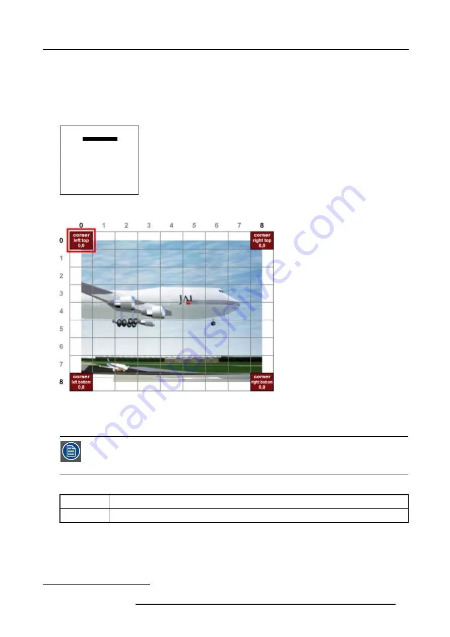
The
COL
&
ROW
(Column and Rows) indicator
2
will show the corresponding position of the selected Corner and an indication
box will be displayed on the screen. (image 6-17)
GEOMETRY DISTORTION
corner left top
col = 0
row = 0
pixels x = 0
y = 0
subpixels x = 0
y = 0
Menu 6-57
Image 6-17
Coarse Corner selections
6.5.7.3.3
Corner adjustment
To change a setting, only the method using the arrow keys is mentioned in the following procedures, the
projector will need to recalculate every adjustment step.
For coarse adjustments it is also possible to enter the new value directly with the numeric keys on the RCU
or local keypad.
What is Pixel and Subpixel adjustment ?
Pixel
Coarse adjustment, this will shift the Corner in steps of 1 pixel
Subpixel
Fine tuning adjustment, this will shift the Corner in steps of 1/32 of a pixel
2. This
COL
&
ROW
indicates the position of the selected grid point within the 81 zones.
R5976781 TRACE+ 14/09/2004
67
Summary of Contents for Trace+ R9040341
Page 1: ...Trace Owner s Manual R9040341 R5976781 00 14 09 2004 ...
Page 4: ......
Page 8: ...Table of contents 4 R5976781 TRACE 14 09 2004 ...
Page 15: ...2 Packaging and Dimensions Image 2 5 Bottom View Dimensions R5976781 TRACE 14 09 2004 11 ...
Page 16: ...2 Packaging and Dimensions 12 R5976781 TRACE 14 09 2004 ...
Page 32: ...4 Trace Connections 28 R5976781 TRACE 14 09 2004 ...
Page 144: ...8 Service Mode 140 R5976781 TRACE 14 09 2004 ...
Page 146: ...9 Standard Source Files 142 R5976781 TRACE 14 09 2004 ...


