background image

Installation guidelines

3-1

5975638 BARCOGRAPHICS 1209s 010797

3

INSTALLATION GUIDELINES

Installation guidelines

Careful  consideration  of  things  such  as  image  size,  ambient  light  level,  projector  placement  and  type  of  screen  to  use  are

critical  to  optimize  the  use  of  the  projection  system.

Environment

Do not install the projection system in a site near heat sources such

as  radiators  or  air  ducts,  or  in  a  place  subject  to  direct  sunlight,

excessive dust or humidity. Be aware that room heat rises to the

ceiling; Make sure  the temperature near the installation site is not

excessive.

What about ambient light ?

The ambient light level of any room is made up of direct or indirect

sunlight and the light fixtures in the room. The amount of ambient light

will determine how bright the image will appear. So, avoid direct light

on the screen as much as possible.

Windows that face the screen should be covered by opaque drapery

while the set is being viewed. It is desirable to install the projecting

system in a room whose walls and floor are of non-reflecting material.

The use of recessed ceiling lights and a method of dimming those

lights to an acceptable level is also important. Too much ambient light

results in a ‘wash out’ of the projected image. This appears as less

contrast between the darkest and lightest parts of the image. With

bigger screens, the ‘wash out’ becomes more important. As a general

rule, darken the room to the point where there is just sufficient light

to read or write comfortably. Spot lighting is desirable for illuminating

small areas so that interference with the screen is minimal.

Which screen type?

There  are  two  major  categories  of  screens  used  for  projection

equipment. Those used for front projected images and those for rear

projection  applications.

Screens are rated by how much light they reflect (or transmit in case

of  rear  projection  systems)  given  a  determined  amount  of  light

projected toward them. The ‘GAIN’ of a screen is the term used.  Front

and rear screens are both rated in terms of gain. The gain of screens

range from a white matte screen with a gain of 1 (x1) to a brushed

aluminized screen with a gain of 10 (x10) or more.  Another important

consideration  is  the  degree  the  screen's  gain  varies  with  the

horizontal and vertical viewing angle. The choice between higher and

lower gain screens is largely a matter of personal preference.

In considering the type of screen to choose, determine where the

viewers will be located and go for the highest gain screen possible.

A  high  gain  screen  will  provide  a  brighter  picture  but  reduce  the

viewing  angle.

For  more  information  about  screens,  contact  your  local

screen  supplier.

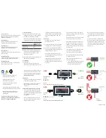
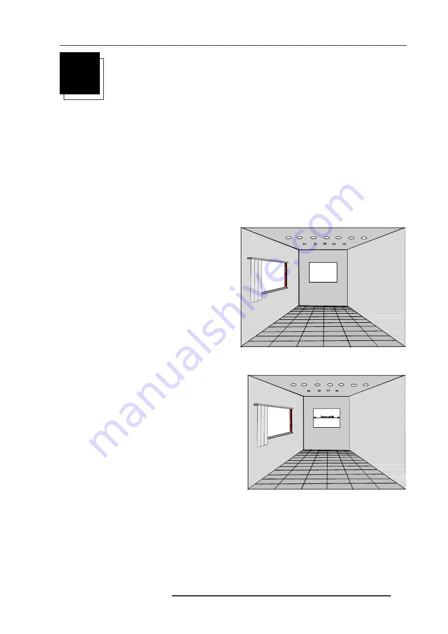
What image size?  How big should the image

be?

The projector is designed for projecting an image width from 2m (6.6')

to 3m (10')  with HD120 lenses and with an aspect ratio of 4 to 3. It

leaves the BARCO factory, adjusted as a ceiling/front projector for

a  screen  width  of  2.4m  (7.8').  Changing  the  image  size  from  the

factory preset size requires a realignment of the projector.

All manuals and user guides at all-guides.com

Summary of Contents for R9000972

Page 1: ...R9000972 R9000977 INSTALLATION MANUAL GRAPHICS 1209s All manuals and user guides at all guides com a l l g u i d e s c o m...

Page 2: ...BARCO PROJECTION SYSTEMS Date 040598 Art No R5975638 R9000972 R9000977 INSTALLATION MANUAL GRAPHICS 1209s Rev 01 All manuals and user guides at all guides com...

Page 3: ...V May 1998 All rights reserved Trademarks are the rights of their respective owners BARCOnv ProjectionSystems Noordlaan5 B 8520Kuurne Belgium Tel 32 56 368211 Fax 32 56 351651 E mail sales bps barco c...

Page 4: ...ontal scan switches 4 3 Vertical scan switch 4 3 PROJECTORSET UP Setting the projector address 5 2 Power upmode 5 3 Operational mode 5 3 Stand By mode 5 3 Baud Rate for communication with a computer 5...

Page 5: ...o the projector 7 4 Connecting a VS05 source selector to the projector 7 4 Connecting an IR Remote Receiver 800 to the projector 7 4 INSTALLATIONADJUSTMENTMODE Access to Installation Adjustment Mode 8...

Page 6: ...or from 120Vac to 230 Vac If you are not sure of the type of AC power available consult your dealer or local power company 2 This product is equipped with a 3 wire grounding plug a plug having a third...

Page 7: ...service personnel under the following condi tions A When the power cord or plug is damaged or frayed B If liquid has been spilled into the equipment C If the product has been exposed to rain or water...

Page 8: ...3 11 1 Owner s Manual 1 Installation Manual 1 Adjustment Manual IRIS To open the banding around the carton pull out the clip as shown below Take the projector out of its shipping carton and place it o...

Page 9: ...nsions in mm Dimensions m m inch L1 1174 46 2 L2 1014 39 9 L3 1000 39 37 L4 735 28 9 L5 110 4 33 L6 265 10 43 W1 782 30 8 W2 665 26 2 H1 355 13 9 H2 315 12 4 H3 219 8 62 H4 101 3 98 H5 121 4 76 L1 L2...

Page 10: ...where there is just sufficient light to read or write comfortably Spot lighting is desirable for illuminating small areas so that interference with the screen is minimal Which screen type There are tw...

Page 11: ...the projector To indicate a correct installation position it is necessary to know The distance from projector to ceiling in case of Ceiling mounted or the distance from projector to floor in case of...

Page 12: ...upported with locking hinge Open with care and support the cover with your hand Lock screws Removing the top cover Duringsomeinstallations itwillbeconvenienttoremovethetopcover from the projector tota...

Page 13: ...ning the projector s top cover see Access to controls WARNING TURN OFF PROJECTOR AND UNPLUG THE POWER CORD BEFORE CHANGING THE SCAN DIRECTION Open the top cover and remove it from the projector see p...

Page 14: ...sion switch to the correct position After setting the scan switches close the metal protection plate and secure it with the retaining screws Close the top cover and reconnect the power cord to the wal...

Page 15: ...PASSWORD CHANGELANGUAGE RUNTIME DYNAMICASTIGMATISM MORE Select with or then ENTER EXIT to return Proj address 001 Soft Version 6 00 Config Ceiling Front Baudrate PC 9600 Text ON Serial No 103589552 GR...

Page 16: ...ews on the rear side of the metal frame Lift up the metal cover plate and pivot to the lens side The controller is mounted on the back side StdBY MAIN POWER PROCESSOR CYC BLOCK MATCH ERROR RCU RCVDS P...

Page 17: ...e values associated to those DIP switches gives the address As shown in the table if Switch No 1 is set to ON it represents a decimal value of 128 Switch No 2 for 64 Switch No 3 for 32 and so forth In...

Page 18: ...ion speed between the projector and the computer has 8 possible settings With DIP Switch No 6 No 7 and No 8 of the 8 DIP switches on the controller board labelled as Baud rate code sum it is possible...

Page 19: ...out password setting and reprogramming the pass word see Installation adjustment When the password menus are disabled adjust mode is unpro tected the adjust mode can be selected by pressing the ADJUST...

Page 20: ...plug proceed as follows The yellow green wire is ground and must be connected to the terminal in the plug which is marked by the letter E or by the safety earth symbol or colored yellow and green The...

Page 21: ...ollow the procedure as described below to adapt the voltage WARNING turn off the projector and be sure the AC Power Cord is unplugged from the wall outlet before starting the procedure Open the top co...

Page 22: ...e projector is set to start up with a full white image the Projector warm up menu will be displayed for 30 seconds Start up with Warm up period If no action is taken a white image will be displayed fo...

Page 23: ...will be displayed Please use EXIT to leave this procedure Start up without Warm up period IfEXITispressed thewarmupperiodwillbeskippedandtheprojector is immediately ready for use Warning Skipping thi...

Page 24: ...or with separate Tri 4 5 RGB with Tri level sync 7 level sync or with separate Horizontal and Vertical Tri level sync R Y Y B Y with Tri level sync on Y or with separate Tri level sync or with separat...

Page 25: ...select the RGB analog Input Press the digit button 3 on the RCU or the local keypad S1ForceNegativeSync ON yes R81 Hsync R101 Vsync R41 Blue R21 Green R1 Red S2BlueinGreen ON yes Line termination 75 r...

Page 26: ...t 4 5 The projector automatically detects where the sync signal is located An interface is recommended when connecting a computer and local monitor to the projector BARCO provides the following interf...

Page 27: ...ideo sources 3 S Video Sources and 1 RGB analog or component Video source to the projector In addition the audio signal associated with the source can be switched to an audio amplifier VS05 order no R...

Page 28: ...requested to enter the 4 digit password Enter the digits with the numeric keys on the RCU or the local keypad Installation Raster Centering Projector Distance Optical Lens Focusing Scheimpflug Adjustm...

Page 29: ...and rotating the lens barrel until the center of the image is clearly focused The corners of the projected image are focused by loosening the wing nut at the front end of the lens and rotating the le...

Page 30: ...T faceplate Press ENTER to activate the raster on the Red CRT faceplate Shift the Red raster with the control stick until the raster is centered on the CRT faceplate Press ENTER to activate the raster...

Page 31: ...irs ENTER continue EXIT to return Press ENTER to start the CRT angle adjustment procedure Press ENTER to continue with the crosshairs alignment Press EXIT to return to the previous menu Press ADJUST t...

Page 32: ...projection angle adjustment CRT PROJECTION ANGLE ADJUSTMENT Align crosshairs ENTER continue EXIT to return Blue crosshair Green crosshair Move the blue CRT to the out side away from the green CRT Blu...

Page 33: ...nally the focus from left top to right bottom by turning screw A4 located under the green lens 5 5 1 8 51 1 72 867 6 03 8 255 7 216 72 567 226 1 7 255 6321 1 6 85 7 1876 72 6 03 8 8670 17 6 0 7 352 72...

Page 34: ...then ENTER EXIT to return After finishing the Installation Adjustment Procedures the main menu returns on the screen You are now able to start the alignment procedure for the projector For detailed in...

Page 35: ...Installation adjustment mode 8 8 5975638 BARCOGRAPHICS 1209s 040598 All manuals and user guides at all guides com...

Page 36: ...ojector placement on support b Location of controls for projector position correction 3 Mounting instructions of the cord to lift up the projector a Mounting the cord support on the upper support b Co...

Page 37: ...ndix A BARCO ceiling mount support A 2 5975638 BARCOGRAPHICS 1209s 040598 Projector position corrections Water level adjustment Projector axis adjustment D C All manuals and user guides at all guides...

Page 38: ...next procedure to adjust the G2 1 open both metal cover by loosening the retaining screws on both sides and pivot the covers to the front side of the projector 2 adjust the G2 potentiometers very slow...

Page 39: ...Appendix B G2 adjustment B 2 597638 BARCOGRAPHICS 1209s 040598 All manuals and user guides at all guides com...

Page 40: ...ry out the Blue Gamma Correction 1 Push the control disk up or down to highlight the item BLUE GAMMA CORRECTION in the menu and then press ENTER If EXIT is pressed the projector will return to the Ser...

Page 41: ...box with a bar scale 0 16 will be displayed to visualise the magnitude of the correction 5 Press ENTER to return to the Gamma Corrections menu GAMMA CORRECTIONS BLUE GAMMA CORRECTION Adjust slope wit...

Page 42: ...RE PROTECTION ASSOCIATION STD 704M SIGNAL TRESHOLD LIMIT VALUE Units TRESHOLD LIMIT VALUE Units BASE METAL ALLOYS METALLIC COATINGS FILLER METAL PLUS COATING OR CORE FLUX OTHERS MATERIAL SAFETY DATA S...

Page 43: ...ED FROM THE USE THEREOF VENDORASSUMESNORESPONSABILITYFORINJURYTOVENDEEORTHIRDPERSONSPROXI MATELY CAUSED BY THE MATERIAL IF REASONABLE SAFETY PROCEDURES ARE NOT AD HERED TO AS STIPULATED IN THE DATA SH...

Page 44: ...All manuals and user guides at all guides com...

Page 45: ...All manuals and user guides at all guides com...

Reviews: