background image

Installation adjustment mode

8-2

5975638 BARCOGRAPHICS 1209s 040598

Important  :  Access  to  adjustments

The top cover of the projector should be removed in order to gain

access to the adjustments.
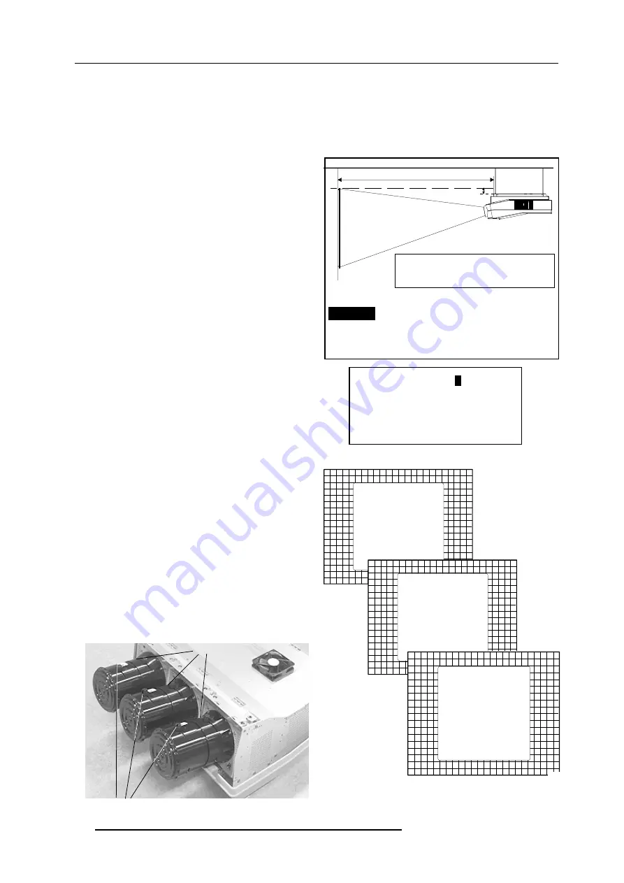
Projector  Distance

On the screen, a drawing will be displayed together with parameters

indicating a correct installation position.

To  change  the  screen  width  :

1 Push the control disk to the left or to the right to highlight the item

SW 

 in the "Projector Distance 1" menu and then press 

TEXT

.

If 

ENTER

 is pressed, the "Optical Lens Focusing" will be displayed.

If 

EXIT

 is pressed, the projector will return to the previous menu.

2 After 

TEXT

 is pressed, the next menu "Projector Distance 2" will

be  displayed  on  the  screen.  It  allows  the  user  to  change  the

Screen  width.

3 Push the control disk to the left or to the right to highlight the digit

needed to be changed, and enter the desired digit with the numeric

keys on the RCU or the local keypad.

4 Press 

ENTER

 to confirm the changes. The projector will re-display

the "Projector Distance 1" menu with updated values for the three

parameters.

5 Press 

ENTER

 to continue with the "Optical Lens Focusing".

If 

EXIT

 is pressed, the projector will return to the previous menu.

The same applies to the PD (projector distance). You can use the

above-mentioned procedure to obtain a correct updated value of SW

(screenwidth) after entering a new value of PD (projector distance).

Optical Lens Focusing

The  optical  focusing  procedure  is  performed  separately  for  each

lens.  The appropriate CRT will be switched on as the user proceeds

through the optical focusing adjustment sequence.

Each lens has two focus adjustment points, one at the rear of the lens

and one at the front. The center of the projected image is focused by

loosening the wing nut at the rear  end of the lens and rotating the

lens barrel until the center of the image is clearly focused. The corners

of the projected image are focused by loosening the wing nut at the

front end of the lens and rotating the lens barrel until the corners of

the image are clearly focused. Repetition of these adjustments may

be necessary to optimize optical focusing.

Press 

ENTER

 to continue. After finishing focusing of the three lenses,

press 

ENTER

 to enter the Raster centering.

Press 

EXIT

 to return to operational mode.

Press 

ADJUST 

key to return to operational mode.

A = Correction value

PD= Perpendicular distance between screen and projector

SW= Screen width

SCREENWIDTH =  

2


, 6 0  m

Select with arrow keys; reprogram with numeric keys and

then <ENTER> to confirm.

Maximum screenwidth = 6 m
Maximum proj. distance = 8,1 m.

SW = 2.6 m

PD= 3.64m

A=12 cm

Select with arrow keys; <TEXT> to reprogram

<ENTER> to continue; <EXIT> to return.

WARNING: ONLY FOR STANDARD PROJECTORS !!

OPTICAL LENS FOCUSING

<ENTER> to continue
<EXIT> to return

1. LOOSEN THE NUT ON THE 
   REAR OF THE XXXX LENS,
   ROTATE THE LENS BARREL
   TO FOCUS THE CENTER 
   OF THE IMAGE,
   THEN TIGHTEN THE NUT
2. LOOSEN THE NUT ON THE 
   FRONT OF THE XXXX LENS
   AND ROTATE THE FRONT 
   SECTION OF THE LENS TO 
   FOCUS THE CORNERS OF THE 
   IMAGE, THEN TIGHTEN THE NUT.

150

OPTICAL LENS FOCUSING

<ENTER> to continue
<EXIT> to return

1. LOOSEN THE NUT ON THE 
   REAR OF THE XXXX LENS,
   ROTATE THE LENS BARREL
   TO FOCUS THE CENTER 
   OF THE IMAGE,
   THEN TIGHTEN THE NUT
2. LOOSEN THE NUT ON THE 
   FRONT OF THE XXXX LENS
   AND ROTATE THE FRONT 
   SECTION OF THE LENS TO 
   FOCUS THE CORNERS OF THE 
   IMAGE, THEN TIGHTEN THE NUT.

Center  focusing

Corner  focusing

$

3'

VFUHHQ

SURMHFWRU

FHLOLQJ

All manuals and user guides at all-guides.com

Summary of Contents for R9000972

Page 1: ...R9000972 R9000977 INSTALLATION MANUAL GRAPHICS 1209s All manuals and user guides at all guides com a l l g u i d e s c o m...

Page 2: ...BARCO PROJECTION SYSTEMS Date 040598 Art No R5975638 R9000972 R9000977 INSTALLATION MANUAL GRAPHICS 1209s Rev 01 All manuals and user guides at all guides com...

Page 3: ...V May 1998 All rights reserved Trademarks are the rights of their respective owners BARCOnv ProjectionSystems Noordlaan5 B 8520Kuurne Belgium Tel 32 56 368211 Fax 32 56 351651 E mail sales bps barco c...

Page 4: ...ontal scan switches 4 3 Vertical scan switch 4 3 PROJECTORSET UP Setting the projector address 5 2 Power upmode 5 3 Operational mode 5 3 Stand By mode 5 3 Baud Rate for communication with a computer 5...

Page 5: ...o the projector 7 4 Connecting a VS05 source selector to the projector 7 4 Connecting an IR Remote Receiver 800 to the projector 7 4 INSTALLATIONADJUSTMENTMODE Access to Installation Adjustment Mode 8...

Page 6: ...or from 120Vac to 230 Vac If you are not sure of the type of AC power available consult your dealer or local power company 2 This product is equipped with a 3 wire grounding plug a plug having a third...

Page 7: ...service personnel under the following condi tions A When the power cord or plug is damaged or frayed B If liquid has been spilled into the equipment C If the product has been exposed to rain or water...

Page 8: ...3 11 1 Owner s Manual 1 Installation Manual 1 Adjustment Manual IRIS To open the banding around the carton pull out the clip as shown below Take the projector out of its shipping carton and place it o...

Page 9: ...nsions in mm Dimensions m m inch L1 1174 46 2 L2 1014 39 9 L3 1000 39 37 L4 735 28 9 L5 110 4 33 L6 265 10 43 W1 782 30 8 W2 665 26 2 H1 355 13 9 H2 315 12 4 H3 219 8 62 H4 101 3 98 H5 121 4 76 L1 L2...

Page 10: ...where there is just sufficient light to read or write comfortably Spot lighting is desirable for illuminating small areas so that interference with the screen is minimal Which screen type There are tw...

Page 11: ...the projector To indicate a correct installation position it is necessary to know The distance from projector to ceiling in case of Ceiling mounted or the distance from projector to floor in case of...

Page 12: ...upported with locking hinge Open with care and support the cover with your hand Lock screws Removing the top cover Duringsomeinstallations itwillbeconvenienttoremovethetopcover from the projector tota...

Page 13: ...ning the projector s top cover see Access to controls WARNING TURN OFF PROJECTOR AND UNPLUG THE POWER CORD BEFORE CHANGING THE SCAN DIRECTION Open the top cover and remove it from the projector see p...

Page 14: ...sion switch to the correct position After setting the scan switches close the metal protection plate and secure it with the retaining screws Close the top cover and reconnect the power cord to the wal...

Page 15: ...PASSWORD CHANGELANGUAGE RUNTIME DYNAMICASTIGMATISM MORE Select with or then ENTER EXIT to return Proj address 001 Soft Version 6 00 Config Ceiling Front Baudrate PC 9600 Text ON Serial No 103589552 GR...

Page 16: ...ews on the rear side of the metal frame Lift up the metal cover plate and pivot to the lens side The controller is mounted on the back side StdBY MAIN POWER PROCESSOR CYC BLOCK MATCH ERROR RCU RCVDS P...

Page 17: ...e values associated to those DIP switches gives the address As shown in the table if Switch No 1 is set to ON it represents a decimal value of 128 Switch No 2 for 64 Switch No 3 for 32 and so forth In...

Page 18: ...ion speed between the projector and the computer has 8 possible settings With DIP Switch No 6 No 7 and No 8 of the 8 DIP switches on the controller board labelled as Baud rate code sum it is possible...

Page 19: ...out password setting and reprogramming the pass word see Installation adjustment When the password menus are disabled adjust mode is unpro tected the adjust mode can be selected by pressing the ADJUST...

Page 20: ...plug proceed as follows The yellow green wire is ground and must be connected to the terminal in the plug which is marked by the letter E or by the safety earth symbol or colored yellow and green The...

Page 21: ...ollow the procedure as described below to adapt the voltage WARNING turn off the projector and be sure the AC Power Cord is unplugged from the wall outlet before starting the procedure Open the top co...

Page 22: ...e projector is set to start up with a full white image the Projector warm up menu will be displayed for 30 seconds Start up with Warm up period If no action is taken a white image will be displayed fo...

Page 23: ...will be displayed Please use EXIT to leave this procedure Start up without Warm up period IfEXITispressed thewarmupperiodwillbeskippedandtheprojector is immediately ready for use Warning Skipping thi...

Page 24: ...or with separate Tri 4 5 RGB with Tri level sync 7 level sync or with separate Horizontal and Vertical Tri level sync R Y Y B Y with Tri level sync on Y or with separate Tri level sync or with separat...

Page 25: ...select the RGB analog Input Press the digit button 3 on the RCU or the local keypad S1ForceNegativeSync ON yes R81 Hsync R101 Vsync R41 Blue R21 Green R1 Red S2BlueinGreen ON yes Line termination 75 r...

Page 26: ...t 4 5 The projector automatically detects where the sync signal is located An interface is recommended when connecting a computer and local monitor to the projector BARCO provides the following interf...

Page 27: ...ideo sources 3 S Video Sources and 1 RGB analog or component Video source to the projector In addition the audio signal associated with the source can be switched to an audio amplifier VS05 order no R...

Page 28: ...requested to enter the 4 digit password Enter the digits with the numeric keys on the RCU or the local keypad Installation Raster Centering Projector Distance Optical Lens Focusing Scheimpflug Adjustm...

Page 29: ...and rotating the lens barrel until the center of the image is clearly focused The corners of the projected image are focused by loosening the wing nut at the front end of the lens and rotating the le...

Page 30: ...T faceplate Press ENTER to activate the raster on the Red CRT faceplate Shift the Red raster with the control stick until the raster is centered on the CRT faceplate Press ENTER to activate the raster...

Page 31: ...irs ENTER continue EXIT to return Press ENTER to start the CRT angle adjustment procedure Press ENTER to continue with the crosshairs alignment Press EXIT to return to the previous menu Press ADJUST t...

Page 32: ...projection angle adjustment CRT PROJECTION ANGLE ADJUSTMENT Align crosshairs ENTER continue EXIT to return Blue crosshair Green crosshair Move the blue CRT to the out side away from the green CRT Blu...

Page 33: ...nally the focus from left top to right bottom by turning screw A4 located under the green lens 5 5 1 8 51 1 72 867 6 03 8 255 7 216 72 567 226 1 7 255 6321 1 6 85 7 1876 72 6 03 8 8670 17 6 0 7 352 72...

Page 34: ...then ENTER EXIT to return After finishing the Installation Adjustment Procedures the main menu returns on the screen You are now able to start the alignment procedure for the projector For detailed in...

Page 35: ...Installation adjustment mode 8 8 5975638 BARCOGRAPHICS 1209s 040598 All manuals and user guides at all guides com...

Page 36: ...ojector placement on support b Location of controls for projector position correction 3 Mounting instructions of the cord to lift up the projector a Mounting the cord support on the upper support b Co...

Page 37: ...ndix A BARCO ceiling mount support A 2 5975638 BARCOGRAPHICS 1209s 040598 Projector position corrections Water level adjustment Projector axis adjustment D C All manuals and user guides at all guides...

Page 38: ...next procedure to adjust the G2 1 open both metal cover by loosening the retaining screws on both sides and pivot the covers to the front side of the projector 2 adjust the G2 potentiometers very slow...

Page 39: ...Appendix B G2 adjustment B 2 597638 BARCOGRAPHICS 1209s 040598 All manuals and user guides at all guides com...

Page 40: ...ry out the Blue Gamma Correction 1 Push the control disk up or down to highlight the item BLUE GAMMA CORRECTION in the menu and then press ENTER If EXIT is pressed the projector will return to the Ser...

Page 41: ...box with a bar scale 0 16 will be displayed to visualise the magnitude of the correction 5 Press ENTER to return to the Gamma Corrections menu GAMMA CORRECTIONS BLUE GAMMA CORRECTION Adjust slope wit...

Page 42: ...RE PROTECTION ASSOCIATION STD 704M SIGNAL TRESHOLD LIMIT VALUE Units TRESHOLD LIMIT VALUE Units BASE METAL ALLOYS METALLIC COATINGS FILLER METAL PLUS COATING OR CORE FLUX OTHERS MATERIAL SAFETY DATA S...

Page 43: ...ED FROM THE USE THEREOF VENDORASSUMESNORESPONSABILITYFORINJURYTOVENDEEORTHIRDPERSONSPROXI MATELY CAUSED BY THE MATERIAL IF REASONABLE SAFETY PROCEDURES ARE NOT AD HERED TO AS STIPULATED IN THE DATA SH...

Page 44: ...All manuals and user guides at all guides com...

Page 45: ...All manuals and user guides at all guides com...

Reviews: