background image

2. Replacing the analyzer
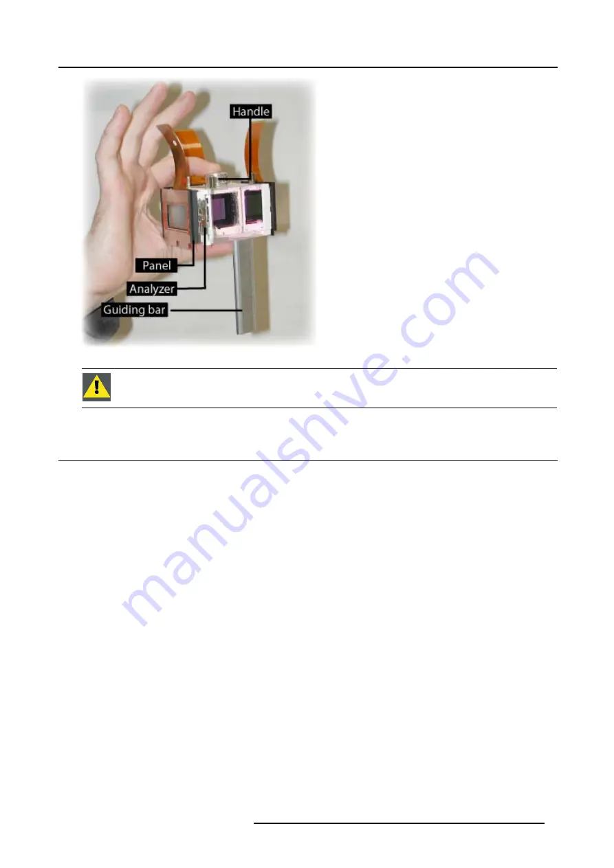
Image 2-5

C

AUTION

:

Never touch the glass surfaces of the cube (only the top and bottom surfaces) !

2.2 Removing the Analyzer assembly

How to remove the Analyzers ?

1. Place the X-Cube upside down on its handle (flat cables downwards) (image 2-6)

Caution:

Never put the cube with the panels on the table ! This can cause convergence errors and scratches on the panels.
(image 2-7)

2. Remove carefully the analyzer locking spring by pushing it gently out at the upper side and sliding it out of the bottom hook.

(image 2-8)

Caution:

Make gentle movements as the white parts are very brittle.

3. Take the cube between the fingers and slide the analyzer out of the X-Cube (image 2-9)

R5976879 ANALYZER KIT FOR ICON 03/03/2005

5

Summary of Contents for R845052K

Page 1: ...Analyzer kit for iCon Installation Manual R845052K R5976879 00 03 03 2005 ...

Page 2: ...Barco nv Presentations Noordlaan 5 8520 Kuurne Phone 32 56 36 82 11 Fax 32 56 35 86 51 E mail presentations bid barco com Visit us at the web www barco com Printed in Belgium ...

Page 3: ...The delivered part consists of a metallic frame holding 2 glass plates The image shows an assembly corresponding to the Red and the Blue analyzer The Green analyzer s metallic frame is mirrored Partnumber Description R845052K Analyzer kit R G B CO R5976879 ANALYZER KIT FOR ICON 03 03 2005 1 ...

Page 4: ...1 Kit description 2 R5976879 ANALYZER KIT FOR ICON 03 03 2005 ...

Page 5: ... X Cube 1 Loosen the 4 screws respect the order 4 1 and remove the X Cube fixation plate image 2 1 2 Disconnect the flat cables image 2 2 3 Turn the locking screw 1 4 turn clockwise to unlock the Cube see the screening on the X Cube fixation plate image 2 3 im age 2 4 4 Hold the X Cube assembly at the handle and lift it vertically Caution Be careful not to touch any of the surrounding polarisers I...

Page 6: ...e X Cube locking screw A X Cube locking screw CUBE LOCKED CUBE LOOSE Image 2 4 Screening on the X Cube fixation plate Handling the X Cube Always hold the X Cube between the fingers at the handle and the bottom surface 4 R5976879 ANALYZER KIT FOR ICON 03 03 2005 ...

Page 7: ...aution Never put the cube with the panels on the table This can cause convergence errors and scratches on the panels image 2 7 2 Remove carefully the analyzer locking spring by pushing it gently out at the upper side and sliding it out of the bottom hook image 2 8 Caution Make gentle movements as the white parts are very brittle 3 Take the cube between the fingers and slide the analyzer out of the...

Page 8: ...2 Replacing the analyzer Image 2 6 Image 2 7 1 2 3 Image 2 8 6 R5976879 ANALYZER KIT FOR ICON 03 03 2005 ...

Page 9: ...zer in the X Cube image 2 10 2 Position the analyzer so that the hole in the analyzer frame coincides with the conical pin ref4 on the Cube frame At the same time the analyzer frame must be positioned using the 3 references ref1 ref2 ref3 on the cube frame see drawing image 2 11 image 2 12 image 2 13 image 2 14 3 Place back the locking spring to secure the position of the analyzer inverse the oper...

Page 10: ...2 Replacing the analyzer Image 2 10 Image 2 11 Ref1 and Ref2 are the reference points on the cube frame 8 R5976879 ANALYZER KIT FOR ICON 03 03 2005 ...

Page 11: ...o force the analyser in place when bad positioned This may break the white parts of the cube 2 4 Mounting the X Cube How to mount the X Cube 1 Verify that the locking screw is in the open position 2 Grab the X Cube by the handle and insert it in its place by putting the guiding bar into the guide hole see handling the X Cube image 2 15 R5976879 ANALYZER KIT FOR ICON 03 03 2005 9 ...

Page 12: ...ight locked screw position image 2 16 Tip When the locking screw is put in the locked position the cube is pushed along the reference ridge in the right position 4 Place and lock the flat cables 5 Place the X Cube fixation plate and tighten the screws in the order 1 4 see the screening on the plate Image 2 15 Image 2 16 10 R5976879 ANALYZER KIT FOR ICON 03 03 2005 ...

Reviews: