R5906897 /02
Prometheus III
37
1
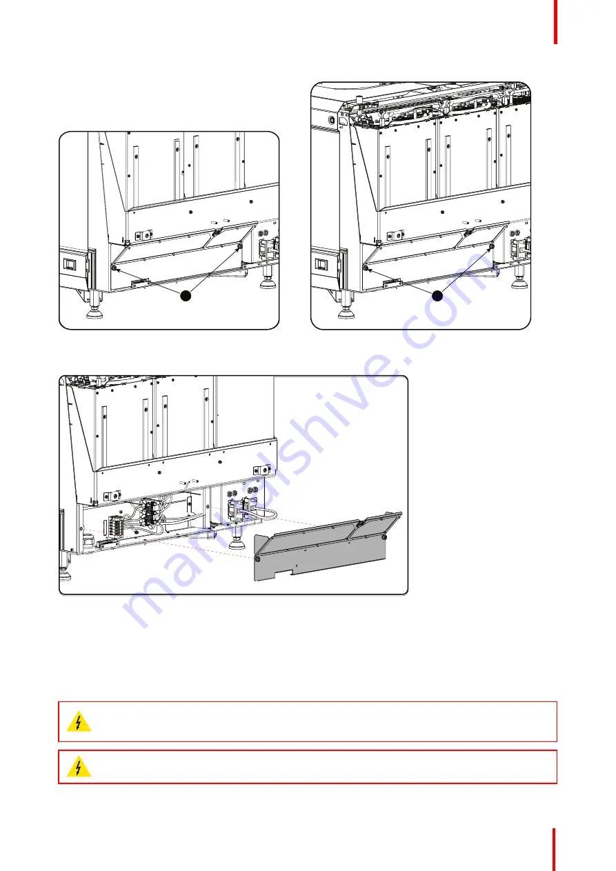
Image 4-5: Power connection cover, captive screws
1
Image 4-6: Power connection cover, captive screws
3.
Slide off the power connection cover.
Image 4-7: Terminal strip accessible
The terminal strip and connection plate is accessible.
4.3 Connecting the Prometheus III with the power
net
WARNING:
The total electrical installation should be protected by an appropriate rated and readily
accessible disconnect switch, circuit breakers and ground fault current interrupters. The installation
shall be done according to the local electrical installation codes.
WARNING:
Make sure that the voltage range of projector matches with the voltage of the local
power net.
Summary of Contents for Prometheus III
Page 1: ...ENABLING BRIGHT OUTCOMES Installation manual Prometheus III...
Page 8: ...R5906897 02 Prometheus III 8...
Page 32: ...R5906897 02 Prometheus III 32 Installation process...
Page 62: ...R5906897 02 Prometheus III 62 Physical installation stand alone cooler...
Page 80: ...R5906897 02 Prometheus III 80 Lenses lens holder...
Page 98: ...R5906897 02 Prometheus III 98 Input communication...
Page 100: ...R5906897 02 Prometheus III 100 Installing a HDD into the ICMP ICMP...
Page 132: ...R5906897 02 Prometheus III 132 Communicator Touch Panel...
Page 148: ...R5906897 02 Prometheus III 148 Removal and installation of the projector covers...
Page 152: ...R5906897 02 Prometheus III 152 Preventative maintenance actions...
Page 170: ...R5906897 02 Prometheus III 170 Convergence...
Page 176: ...R5906897 02 Prometheus III 176 Color calibration...
Page 199: ...R5906897 02 Prometheus III 199 Environmental Information...


