background image

STEP2: The device and its components

7

4

STEP2: The device and its components

4.1

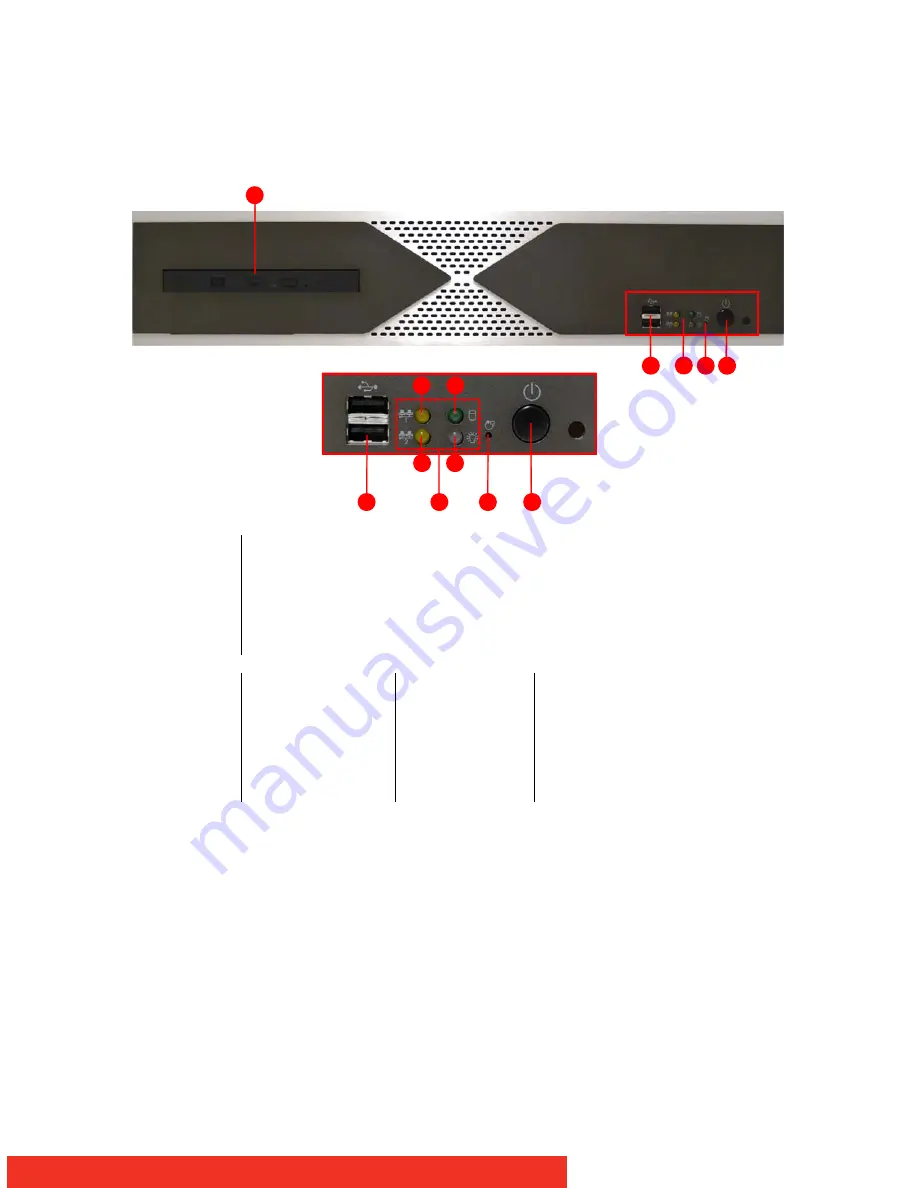
Front View NGS-V161

 Figure 1: Front view

1

DVD-RW drive

2

2 x USB ports

3

Status LEDs (

L1, L2, L3, L4

)

4

Reset button

5

Power Switch

L1

L2

L3
L4

Ethernet Port 1 Led

Ethernet Port 2 Led

Hard Disk Led
Power Led

Green
Orange (flashing)
Green
Orange (flashing)
Green
Red

When LAN is connected 
When Data is being accessed
When LAN is connected
When Data is being accessed
When system is powered on 
When Hard Disk is being accessed

1

4

5

2

3

L1

L3

L2

L4

4

5

2

3

Summary of Contents for NGS-V161

Page 1: ...NGS V161 Installation manual R59112800 00 ...

Page 2: ...2 Intentionally left blank ...

Page 3: ...Customer notice 3 1 Customer notice Thank you for buying Barco Barco is a world leader in display and visualization solutions We are convinced that you will enjoy our products ...

Page 4: ...ode Supports NTSC and PAL video input 16 channel audio encode up to 16 bit 32 kHz Intel Q35 ICH9DO Intel Core 2 Duo processor DDR2 memory Dual gigabit Ethernet Scalable Video Coding SVC 2 2 Content Quick Start Guide This installation manual is designed to aid quick installation and set up of your new NGS V161 however should you experience any problems not covered in this guide please refer to the ...

Page 5: ...l injury or death CAUTION Cautions presented in this manual provide information which if not adhered to may result in damage to the equipment NOTE Notes presented in this manual provide information which emphasize points significant to understand and operate the unit IMPORTANT Important presented in this manual provide information which is important to highlight 2 4 Change record Revision Date Des...

Page 6: ...86 MGS software CDROM R33044100 Installation Manual R59112800 3 2 Packaging A safe transport of the units can only be guaranteed if the original undamaged package is used for shipping Handle with care when transporting Keep your original packaging It is designed for this unit and is the ideal protection during transportation ...

Page 7: ...Ds L1 L2 L3 L4 4 Reset button 5 Power Switch L1 L2 L3 L4 Ethernet Port 1 Led Ethernet Port 2 Led Hard Disk Led Power Led Green Orange flashing Green Orange flashing Green Red When LAN is connected When Data is being accessed When LAN is connected When Data is being accessed When system is powered on When Hard Disk is being accessed 1 4 5 2 3 L1 L3 L2 L4 4 5 2 3 ...

Page 8: ...ping 2 TV Out via RCA 3 S Video 4 Sequence Monitor 5 Video Input 6 COM Port 7 VGA Connector 8 Line In for audio sources 9 Microphone Port 10 Line Out Port headphone speaker 11 4 USB Ports 12 2 Ethernet Ports 13 DVI D Port 14 Power 15 Audio Input 16 Alarm 14 15 16 1 6 8 3 5 12 13 2 4 7 9 10 11 ...

Page 9: ... Keyboard and Mouse into vacant USB connectors see 2 on the figure above 3 Connect your network to Ethernet port 1 see 3 on the figure above 4 Connect the power cable see 4 on the figure above NOTE The keyboard and mouse can also be plugged into USB connectors on the front side of the unit 1 VGA output connection for control screen 2 4 USB ports keyboard and mouse 3 2 Ethernet ports port 1 left po...

Page 10: ...ssing the Power Switch see 1 on the figure below 2 Insert the MGS software CDROM R33044100 in the CDROM drive see 1 on the figure below as soon as the unit is powered on 3 The Setup procedure starts automatically and takes approximately 15 minutes When the setup is finished the CDROM drive opens and the system reboots auto matically 1 Power Switch 2 CDROM drive 2 1 ...

Page 11: ...f it had not been configured yet the streaming network interface of the unit has the default factory IP address https 172 16 0 2 The browser will display the web interface NOTE Accept the certificate before the web browser opens When the web interface has started its home page can be seen On the left hand side there is a navigation menu which provides access to the different kind of settings Each ...

Page 12: ...settings login to Barco mode or administrator mode 7 3 Changing the IP address via the web interface To change the IP address you first need to be logged in as administrator 3 Use the link Log in at the right top corner of the screen 3 A login and password will be needed here Login admin Password b4rc0 BCD Now go to System settings Network configuration and the following window appears on the scre...

Page 13: ...n using DHCP When DHCP is selected an IP address will be automatically allocated to the unit When Static is selected one can manually change the IP address as shown in the screenshot below After the IP address is changed click the Update button on the right hand side ...

Page 14: ...ce Figure 7 Network configuration using Static After changing the network configuration one should restart the services 3 Go to System settings System access and select Restart Service s 3 Push the update button 3 Select Yes to confirm ...

Page 15: ...owing the workers via the web interface Go to Functional settings workers and the following window appears on the screen Figure 8 List of workers NOTE The workers are listed from 100 to 115 Worker 100 matches input 1 worker 115 matches input 16 ...

Page 16: ... Figure 9 Connecting the video input s IMPORTANT Make sure that all inputs that are connected to the unit have the same format 8 2 Checking the video input s via RTSP One can check the video input s via RTSP NOTE VideoLan Client VLC www videolan org media player is used in this example but any other media player that allows network streaming can be used Open the media player Go to Media Open Netwo...

Page 17: ... Open Network Stream VLC media player Give in the URL to connect to the unit If it had not been configured yet the streaming network interface of the unit has the default factory IP address rtsp 172 16 0 2 fol lowed by the worker worker100 to worker115 ...

Page 18: ...TEP6 Video streaming over the network Figure 11 Enter the network URL NOTE In the example above worker100 is selected One can do this for every worker Push the Play button The video stream should be visible ...

Page 19: ...Further reference 19 9 Further reference To gain full advantage of your new NGS V161 system it is recommended that you study the User Manual that can be found on the CDROM ...

Page 20: ...ew NGS V161 8 5 STEP3 Connecting the components 9 5 1 Cabling and connections 9 6 STEP4 Switching on the system and Setup 10 6 1 Switching On and Setup 10 7 STEP5 Using the MGS web interface 11 7 1 Pre configured network settings 11 7 2 Starting the web interface 11 7 3 Changing the IP address via the web interface 12 7 4 Showing the workers via the web interface 15 8 STEP6 Video streaming over th...

Page 21: ...er On the unit 10 Figure 5 Left Standard mode Barco mode Right Administrator mode 12 Figure 6 Network configuration using DHCP 13 Figure 7 Network configuration using Static 14 Figure 8 List of workers 15 Figure 9 Connecting the video input s 16 Figure 10 Open Network Stream VLC media player 17 Figure 11 Enter the network URL 18 ...

Page 22: ...22 Further reference End of document ...

Reviews: