25
K5902132 (451920612534) /03
MUIP-2112
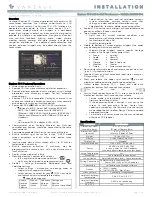
Emissions test
Compliance
Electromagnetic environment
–
Guidance
RF emissions
CISPR 11
Group 1
The MUIP-2112 uses RF energy
only for its internal function.
Therefore, its RF emissions are
very low and are not likely to cause
any interference in nearby
electronic equipment.
RF emissions
CISPR 11
Class B
The MUIP-2112 is suitable for use
in all establishments, including
domestic establishments and those
directly connected to the public low-
voltage power supply network that
supplies buildings used for
domestic purposes.
Harmonic emissions
IEC 61000-3-2
Not applicable
1
Voltage fluctuations/ flicker
emissions
IEC 61000-3-3
Complies
This MUIP-2112 complies with appropriate medical EMC standards on emissions to, and interference from
surrounding equipment. Operation is subject to the following two conditions: (1) this device may not cause
harmful interference, and (2) this device must accept any interference received, including interference that
may cause undesired operation.
Interference can be determined by turning the equipment off and on.
If this equipment does cause harmful interference to, or suffer from harmful interference of, surrounding
equipment, the user is encouraged to try to correct the interference by one or more of the following measures:
•
Reorient or relocate the receiving antenna or equipment.
•
Increase the separation between the equipment and receiver.
•
Connect the equipment into an outlet on a circuit different from that to which the receiver is connected.
•
Consult the dealer or an experienced technician for help.
Electromagnetic immunity
The MUIP-2112 is tested to be used in the electromagnetic environment specified below. The customer or the
user of the MUIP-2112 should assure that it is not used in an environment that exceeds the listed test levels
and limits.
Immunity test
IEC 60601 test levels
Compliance level
Electromagnetic
environment
–
guidance
Electrostatic discharge
(ESD)
IEC 61000-4-2
± 8 kV contact
± 2 kV, ± 4 kV, ± 8 kV, ± 15
kV air
± 8 kV contact
± 2 kV, ± 4 kV, ± 8 kV, ± 15
kV air
Floors should be wood,
concrete or ceramic tile. If
floors are covered with
synthetic material, the
relative humidity should be
at least 30%
Electrical fast transient/
burst
IEC 61000-4-4
± 2 kV for power supply
lines
± 1 kV for input/ output
lines
100 kHz repetition
frequency
± 2 kV for power supply
lines
± 1 kV for input/ output
lines
100 kHz repetition
frequency
Mains power quality
should be that of a typical
commercial or hospital
environment
Surge
IEC61000-4-5
Line to line: ± 0.5 kV, ± 1
kV
Line to ground: ± 0.5 kV, ±
1 kV, ± 2 kV
Line to line: ± 0.5 kV, ± 1
kV
Line to ground: ± 0.5 kV, ±
1 kV, ± 2 kV
Mains power quality
should be that of a typical
commercial or hospital
environment
Voltage dips, short
interruptions and voltage
variations on power supply
input lines
IEC 61000-4-11
0% residual voltage for 0.5
period at 0°, 45°, 90°,
135°, 180°, 225°, 270°
and 315°
0% residual voltage for 0.5
period at 0°, 45°, 90°,
135°, 180°, 225°, 270°
and 315°
Mains power quality
should be that of a typical
commercial or hospital
environment. If the user of
the MUIP-2112 requires
1.
Active power for MUIP-2112 is less than 75 W
Summary of Contents for MUIP-2112
Page 1: ...ENABLING BRIGHT OUTCOMES User Guide 12 5 LCD User Interface MUIP 2112...
Page 4: ...K5902132 451920612534 03 MUIP 2112 4...
Page 8: ...K5902132 451920612534 03 MUIP 2112 8 Welcome...
Page 14: ...K5902132 451920612534 03 MUIP 2112 14 Image 2 10 Installation...
Page 15: ...15 K5902132 451920612534 03 MUIP 2112 Maintenance 3...
Page 17: ...17 K5902132 451920612534 03 MUIP 2112 Important information 4...
Page 34: ...K5902132 451920612534 03 MUIP 2112 34 Important information...
Page 35: ......