background image

11

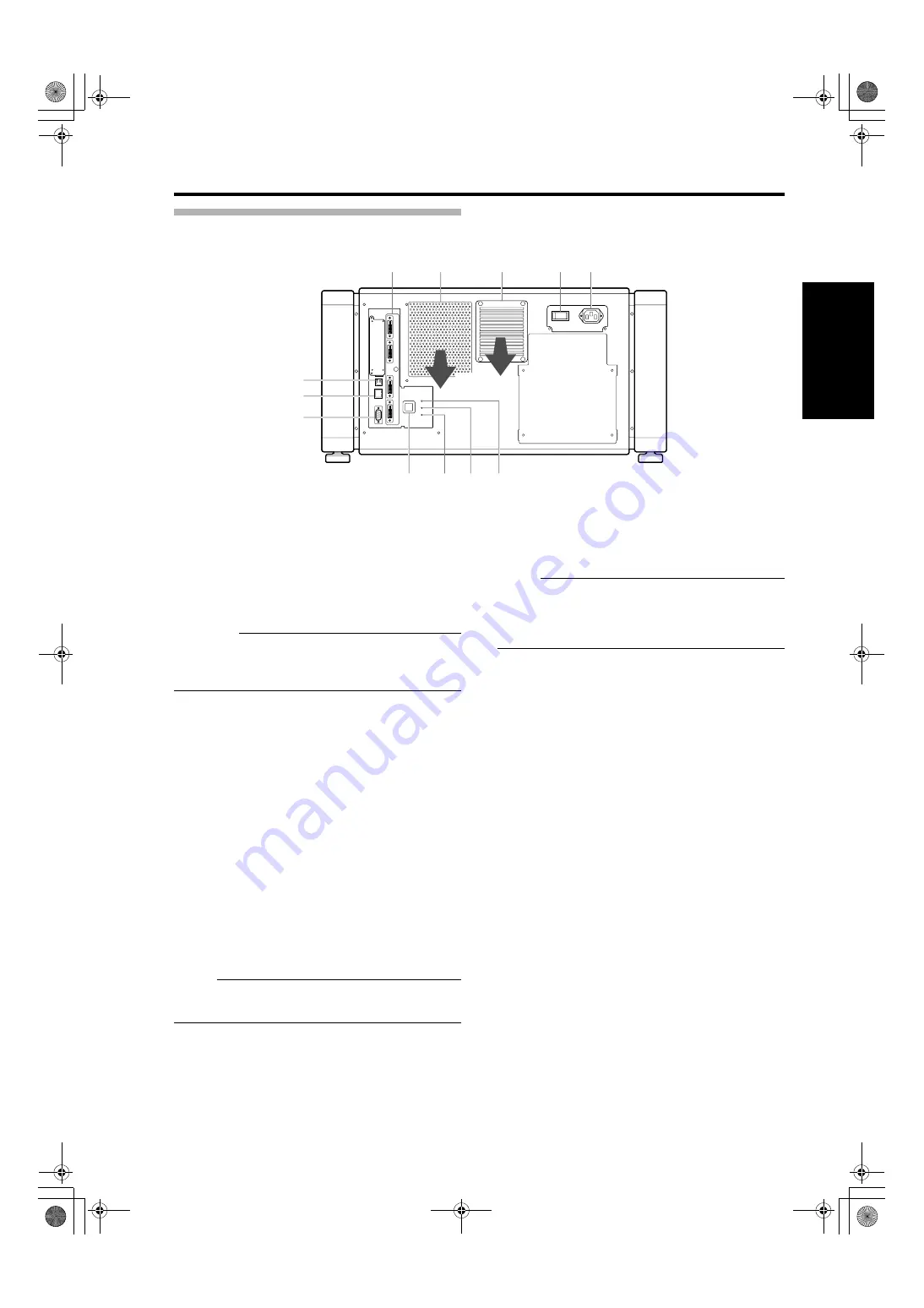
Rear

G

[DVI 1 to 4] Terminal

This is an input terminal for video signals. Connect it to 
the video output terminal of the computer. 
(

A

Page 19, 21)

H

Vent Hole

Warm air exits from the hole after cooling the projector.

CAUTION:                                                                      

Do not block the vent holes with papers, cloth, or soft 
cushions. Doing so may cause heat to trap inside the 
projector and result in fire or malfunction.

I

Vent Hole (For Lamp)

Warm air exits from the hole after cooling the lamp.

J

Main Power Supply Switch

Use this to turn ON/OFF the main power supply of the 
projector unit.

K

AC Power Input Terminal

Connect the supplied cord to this terminal.

L

[STANDBY/ON] Indicator

Lit (Red)

: When in the standby mode.

Lit (Green)

: When power is supplied.

Blinking (Red)

: When cooling down (cool down 

mode). (

A

Page 29)

Blinking (Green) : When the projected image is 

temporarily hidden. (

A

Page 29)

NOTE:                                                                             

For details on indicator displays during warnings, refer 

to “Warnings Using Indicators”. (

A

Page 47)

M

[LAMP] Indicator

This indicator lights up in yellow when the lamp time 
exceeds 1400 hours. 

NOTE:                                                                             

For details on indicator displays during warnings, refer 
to “Warnings Using Indicators”. (

A

Page 47)

A lamp life message appears when the lamp time has 
exceeded 1500 hours. (

A

Page 46)

N

[WARNING] Indicator

This indicator lights up in red when abnormality occurs on 
this projector. For details, refer to “Warnings Using 
Indicators”. (

A

Page 47)

O

[OPERATE I/

B

] Button

Pressing this button for one second or longer when in the 
standby mode (main power supply is ON) turns on the 
power of the projector unit. Pressing it for one second or 
longer when the power is ON switches the projector to 
the standby mode.

P

[RS-232C] Terminal

This is the RS-232C interface-specific terminal. This 
projector can be controlled by connecting it to a computer 
using a RS-232C cable.

Q

[LAN] Terminal

Enables control of this projector using a computer that is 
connected to the network.

R

[USB] Terminal

Enables control of this projector by connecting it to a 
computer.

OPERATE I/

B

DVI 3

USB

LAN

RS-232C

STANDBY/ON

CONTROL

LAMP

WARNING

DVI 4

DVI 1

DVI 2

G

H

I

J

K

L

M

N

O

P

Q

R

Exhaust air

LX-5_EN.book  Page 11  Friday, July 4, 2008  9:35 AM

Summary of Contents for LX-5 SERIES

Page 1: ...e of the cabinet Retain this information for future reference Model No R9011221 Serial No Please study this instruction manual carefully before starting to operate the unit in order to use the unit co...

Page 2: ...ust not be blocked or covered The openings should never be blocked by placing the product on bed sofa rug or similar surface It should not be placed in a built in installation such as a bookcase or ra...

Page 3: ...e characteristics as the original part Unauthorized substitutions may result in fire electric shock or other hazards Upon completion of any service or repairs to this product ask the service technicia...

Page 4: ...ved extension lead or adapter or consult your dealer If nonetheless the mains plug is cut off dispose of the plug immediately to avoid a possible shock hazard by inadvertent connection to the main sup...

Page 5: ...Length Power cord Power supply cord 3 3 m DVI X4 Cable Shielded cable 5 0 m USB Cable Shielded cable 2 0 m LAN Cable Shielded cable 2 0 m RS 232C Cable Shielded cable 1 6 m The inrush current of this...

Page 6: ...Controlling this Projector 22 Turning On the Main Power 23 IP Address Settings 24 Assigning a static IP address 24 Assigning IP Address from the DHCP Server 27 Using the Mail Delivery Feature 27 Conn...

Page 7: ...ilt angle of up to 90 which provides greater flexibility in the location of the projection screen Low power consumption This product helps to save power with a consumption of not more than 1 5 kW User...

Page 8: ...when operating this product NOTE Describes reference information such as functions and restrictions during use A Indicates the page or section to refer to Content of this manual Personal computers or...

Page 9: ...perature around the projector unit When a heater is in use the ceiling may reach a temperature higher than anticipated hence leading to malfunction of the unit Maintenance Procedures oClean dirt on th...

Page 10: ...ION Do not project images with the lens cap attached The lens cap may be deformed due to the heat or the projector may malfunction C Projection Lens optional Zoom lens or short focal length lens is op...

Page 11: ...tor lights up in yellow when the lamp time exceeds 1400 hours NOTE For details on indicator displays during warnings refer to Warnings Using Indicators A Page 47 A lamp life message appears when the l...

Page 12: ...of projector When using two sets of projectors side by side When the projector is suspended NOTE To prevent the projector from falling or toppling it is recommended that the holder be fastened to the...

Page 13: ...ion screen vertically between 0 to 100 and horizontally between 0 to 50 When a short focal length lens optional is in use you can shift the projection screen position vertically between 0 to 30 and ho...

Page 14: ...Zoom lens LXD 1 1 Short focal length lens NOTE When using the lens shift feature do not exceed the range shift amount as shown above If the shift amount exceeds the range as shown shadows will appear...

Page 15: ...o projectors that are arranged side by side Arranging two projectors side by side enhances the brightness level and helps to project images that are sufficiently bright even when the venue is relative...

Page 16: ...1 m 4 42 m 3 58 m 120 Approx 3 05 m 2 63 m 4 83 m 3 91 m 130 Approx 3 30 m 2 85 m 5 24 m 4 25 m 140 Approx 3 56 m 3 07 m 5 65 m 4 58 m 150 Approx 3 81 m 3 29 m 6 06 m 4 91 m 160 Approx 4 06 m 3 51 m 6...

Page 17: ...91 m 90 Approx 2 29 m 1 97 m 2 16 m 100 Approx 2 54 m 2 19 m 2 41 m 110 Approx 2 79 m 2 41 m 2 66 m 120 Approx 3 05 m 2 63 m 2 91 m 130 Approx 3 30 m 2 85 m 3 17 m 140 Approx 3 56 m 3 07 m 3 42 m 150...

Page 18: ...8 2400 4096 2400 4ch Single DVI 1 to DVI 4 Cross 2048 1200 4 Stripes 1024 2400 4096 2160 2ch Dual DVI 1 DVI 3 2 Stripes 2048 2160 4096 2160 4ch Single DVI 1 to DVI 4 Cross 2040 1080 4 Stripes 1024 216...

Page 19: ...g on your DVI D cable the signal may attenuate and the image become unstable Use of DVI D cables compliant with the DDWG standard is recommended DVI 3 DVI 1 DVI 1 DVI 4 DVI 3 DVI 2 DVI 1 DVI 1 DVI 4 D...

Page 20: ...screen appears blue or black depending on the setting when there is no input Connecting Video Signals of the Computer Cont d Computer 1 Computer 2 Output Status Resolution Channel Link Status 2048 12...

Page 21: ...ended CONTROL OPERATE I B DVI 3 USB LAN RS 232C STANDBY ON LAMP WARNING DVI 4 DVI 1 DVI 2 DVI D Cable Sold Separately To DVI Terminal Desktop Computer To DVI Terminal Laptop Computer CONTROL OPERATE I...

Page 22: ...equivalent or higher 100Base TX LAN cables Specifications of PC for Controlling this Projector NOTE Make use of Internet Explorer Ver 6 0 Windows is either registered trademark or trademark of Micros...

Page 23: ...will result in duplication of the IP address and thereby preventing proper access When using multiple units of LX 5 turn on the main power of the second unit and configure accordingly only after conf...

Page 24: ...Check to ensure that the AClient for Microsoft NetworksB and AInternet Protocol TCP IP B check boxes are selected 4 Select AInternet Protocol TCP IP B and click APropertiesB 5 Set the IP address 6 Cli...

Page 25: ...the AActive scriptingB of the Internet Explorer is disabled A Click AToolsB and select AInternet OptionsB B Click in the order of ASecurityB ATrusted SitesB ASitesB C Deselect the check in ARequired s...

Page 26: ...values for AIP AddressB ASubnet MaskB and ADefault GatewayB C Click ASETB NOTE Access from computers may not be sucessful as this projector s IP address has been changed Set and change the computer s...

Page 27: ...exist the projector will start up using the default IP address instead CAUTION Configure the DHCP server such that the same IP address is assigned to the AMac AddressB of this projector by the DHCP s...

Page 28: ...size Press the ATB Tele end of Zoom NOTE The screen size changes each time you click on the inner buttons Fine control The outer buttons change the screen size when they are depressed Coarse control...

Page 29: ...and cause a malfunction Upon using attach the lens cap to prevent soiling of the lens When the projector is not to be used for a long time disconnect the power plug Useful Features During Projection H...

Page 30: ...the power of this unit is off main power is on the AMainB AImageB ASettingB AConvergenceB ALensB and AOptionB menus will be grayed out and will not be selectable Setting Menu Cont d Main DVI Rate Hz P...

Page 31: ...on switches the projector to the cooling mode The power of the projector cannot be turned on during the cooling process 180 seconds Latest Error Displays the latest error number Refer to ALatest Erro...

Page 32: ...tness Red Green Blue 30 to 30 Default Value 0 30 to 30 Default Value 0 30 to 30 Default Value 0 For adjusting the brightness of the red green and blue colors Contrast Red Green Blue 30 to 30 Default V...

Page 33: ...lay Mode Q Single Double Cross For specifying the display mode of the projection screen Single Displays input signals on a single screen Double Displays two different input signals on two screens The...

Page 34: ...ed and blue colors on the image NOTE The green color value is fixed The outer buttons are used for adjustment in units of 1 4 pixels and the inner buttons in units of 1 10 pixels When the image is fli...

Page 35: ...s when the outer button is depressed Focus For adjusting the focus position NOTE The focus position changes each time the inner button is clicked The focus position changes when the outer button is de...

Page 36: ...cally OFF Do not flip image vertically Lamp Power Q 100 to 80 For setting the brightness of the light source lamp NOTE Brightness switches in about a step of 3 between the 80 to 100 range Back Color Q...

Page 37: ...Subnet Mask Default Gateway Mac Address DHCP Q Static IP Default Value 192 168 0 2 Default Value 255 255 255 0 Default Value 192 168 0 254 For configuring the network settings DHCP Select this to acqu...

Page 38: ...B for the error code A Page 48 Setting Menu Cont d Logout host PJ 1 user root E Mail Setting Tset Mail SET SEND E Mail E Mail Address SMTP Server Address E Mail Auth Auth Type Auth User Account Auth P...

Page 39: ...mail authentication feature Auth Type Q PLAIN LOGIN CRAM MD5 For configuring the e mail authentication type PLAIN Set e mail authentication to APLAINB LOGIN Set e mail authentication to ALOGINB CRAM...

Page 40: ...and parameter as well as parameter and parameter 20h CR Designates the terminal of the data 0Dh is not necessary for Asking command Response Data Format Projector PC Upon executing a control command...

Page 41: ...iguring the ADHCP ClientB and AIP AddressB execute ANetwork RestartB Character Hex Meaning 0 30 OFF 1 31 ON Character Hex Meaning 0000 30 30 30 30 Standby state 0001 30 30 30 31 Power ON state 0002 30...

Page 42: ...to appear on the projected image If dirt has entered this product or if you need to purchase the filter please consult your authorized dealer Maintenance Turn off the power of the projector unit and u...

Page 43: ...or plastic products Remove dirt that is attached to the vent holes Do this using a vacuum cleaner Wipe using a cloth if a vacuum cleaner cannot be used Leaving dust attached may prevent adjustment of...

Page 44: ...ne down Turn on the main power supply switch to run the fan and cool down the lamp Turn on the power after about 180 seconds Image is dark Is the lamp near exhaustion Check the ALamp TimeB setting of...

Page 45: ...s the setup position of the projector been shifted Check the setup position of the projector Image disappears suddenly Are the video signals correctly input Check the signals and connection A Page 18...

Page 46: ...riod of 3 minutes during each projection Replace with a new lamp unit For details on replacement of the lamp unit please consult your authorized dealer Out of Range When there is input of video signal...

Page 47: ...r Description STANDBY ON LAMP WARNING 1 1 Light On Yellow About time to replace lamp Lamp time has exceeded 1400 hours 2 When the lamp life has expired Lamp time has exceeded 1500 hours Message displa...

Page 48: ...CPU circuit board 31 Trouble with MAIN circuit board 32 Trouble with DD RB circuit board 33 Trouble with DD G circuit board 40 FAN1 the cooling fan for DD has stopped 41 FAN2 the cooling fan for the l...

Page 49: ...Approx 1 2 m to 6 m Short focal length lens Signal System Digital video 4096 2400 Input format 4096 2160 3840 2400 3840 2160 2048 1200 2048 1080 1920 1200 1920 1080 1600 1200 1280 1024 1024 768 800 60...

Page 50: ...o Signal Pin No Signal 1 TMDS Data 2 13 TMDS Data 3 2 TMDS Data 2 14 TMDS 5 V Power Supply 3 TMDS Data 2 4 Shield 15 Earth 5 V 4 TMDS Data 4 16 Hot Plug Detection 5 TMDS Data 4 17 TMDS Data 0 6 DDC Cl...

Page 51: ...0 127 803 30 688 Projection lens is optional 827 Including the optional projection lens 449 677 36 257 6 342 to 362 199 M10 hole x 12 Tightening depth 10 to 20 457 211 Center of lens 136 26 to 46 317...

Page 52: ...2008 Barco Presentation and Simulation R9011221 PROJECTOR LX 5_EN book Page 52 Friday July 4 2008 9 35 AM...

Reviews: