background image

Connections

3-2

5976053 BARCODATA 808s SP 010799

When starting up the projector, with the power switch or via the stand-by key, the

projector can start up in two ways if the "CRT run in" cycle option is switched OFF.

- full white image (projector warm up) or

- immediate image display.

The way of starting up can be set in the service mode.

Start up with full white image.

The next menu will be displayed for 30 seconds.

a. Start up with warm up period.

If no action is taken, a white image will be displayed for 20 minutes.

This white image will be shifted on the faceplate of the CRT to avoid a CRT burn in.

During this warm up period, it is possible to interrupt this white image projection by

pressing the EXIT key.  The previous menu will be repeated for another 30 seconds

but the remaining time will be indicated.

If EXIT is pressed, the remaining warm up period will be skipped.

During the warm up period, every 30 seconds a text box with the remaining time will

be displayed on the screen for 2 seconds.  This text box will be displayed  each time

in a different place.

If another key, different from EXIT, is pressed, a text box with following text will be displayed :

Please use <EXIT> to leave this procedure.

b. Start up without warm up period.

If the 

EXIT

 key is pressed, the warm up period will be skipped and the projector is immediately ready for

use.

Warning : skipping this warm up procedure can reduce the initial picture quality of the

projected image.

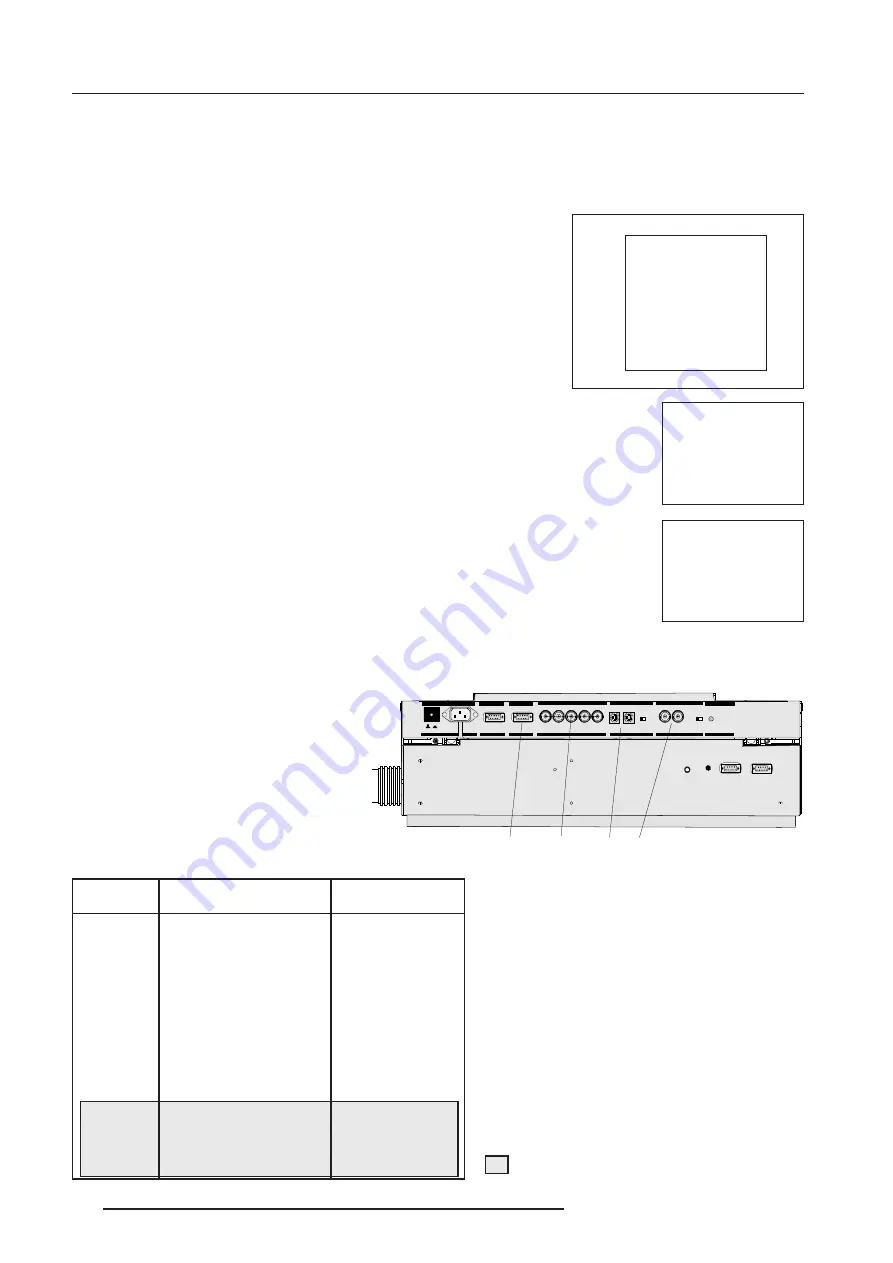
Signal Input Connection to the Projector :

- Composite Video

- S-Video

- RGBS or RGsB

- RGB3S or RG3sB (option)

Only available when the optional Tri-level sync mod-

ule is installed.

Port No

Projector input

Press Digit Button

1

Comp. Video

1

2

S-Video

1

/Comp. Video*

2

3

RGB

2

3

4/5

RGB

2

4 or 5

4/5

Component video

3

6

4/5

RGB with Tri level sync

4

7

4/5

Component video

with Tri-level sync

5

8

1

Input signal Y/C (luma/chroma)

2

Input signal : R, G and B with automatic sync

detection between seperate sync (separate com-

posite sync or with separate Hor and Vert. sync)

or sync on green (composite sync).

3

Input signal : R-Y, Y and B-Y with separate

composite sync  or with separate Hor and Vert.

sync or with composite sync on Y.

4

Input signal : R, G and B with separate Tri level

sync or with Tri-level sync on green.

5

Input signal : R-Y, Y and B-Y with separate Tri

level sync or with composite Tri-level sync.

*

Video or S-Video : switchable in the Picture

Tuning menu.

PROJECTOR WARM UP

A FULL WHITE PATTERN

WILL BE GENERATED FOR

20 MINUTES;

FOR INMEDIATE USE OF

THE PROJECTOR, PRESS

<EXIT>;

WARNING : SKIPPING THIS

PROCEDURE CAN REDUCE

THE INITIAL PICTURE

QUALITY OF THE PROJECTED

IMAGE;

THIS OPTION CAN BE

DISABLED IN THE SERVICE

MENU

REMAINING

PROJECTOR

WARM UP

TIME

18.5 MIN

PLEASE USE

<EXIT> TO

LEAVE THIS

PROCEDURE

21

2))

POWE R  /  MAINS

SHULSKHUDOV

5

*

%

&RPS+6\QF 96\QF

COMM. PORT

PORT  3

PORT  4/5

9QRP

,QRP

)UHT

6HHLQ VWDOODWLRQLQVWUXFWLRQVE HIRUHFR QQHFWLQ JWRWK HVXS SO\
9RLUODQRWLFHGLQ VWDOODWLRQDYDQWGHUDFFRUGHUDXUpVHDX 

9

$PS

+]

69,'(2

2))2 1

2KP

9,'(2

JUHHQRSH UDWLRQ

UHGVWDQGE\

PO RT  2

PORT  1

2))21

2KP

PROJECTOR  MODE

7KLVGHYLFH F RPSOLHVZLWKSDUWRI
WKH)&&UXOHV2SHUDWLRQLVV XEMHFWWR

IROORZ LQJWZ RF RQGLWLRQV7KLV

GHYLFH PD\ QRWFD XVH KDUPIXOLQWHU
IH UH QFH DQGWKLV GHYLFHPXVW

DFFHSWDQ\ LQWH UIH UH QFH UHFH LYHG

LQFOXGLQJLQWHUIHUHQF HWKDWPD \FD XVH

XQGHVLUHGRSHUDWLRQ

5

6

,

1

5

6

2

8

7

,5

5

(

0

2

7

(

56,1

56287

,5

5(027(

PO

R T

 4

/5

PO

RT 

3

CO

MM

. P

OR

T

PORT  2

PO

RT 

1

PR

OJE

CT

O R

 M

OD

E

PO

WE

R  /

 M

AIN

S

All manuals and user guides at all-guides.com

Summary of Contents for DATA 808s SP

Page 1: ...R9002260 R9002269 OWNER S MANUAL DATA 808s SP All manuals and user guides at all guides com...

Page 2: ...BARCO PROJECTION SYSTEMS Date 010799 Art No R5976053 R9002260 R9002269 OWNER S MANUAL DATA 808s SP Revision 00 All manuals and user guides at all guides com...

Page 3: ...9 All rights reserved Trademarks are the rights of their respective owners Printed in Belgium BARCOn v ProjectionSystems Noordlaan5 B 8520Kuurne Belgium Tel 32 56 368211 Fax 32 56 351651 E mail sales...

Page 4: ...rt 4 5 3 5 Connecting a computer to the projector 3 6 Peripheral equipment 3 6 Connecting a RCVDS 05 switcher to the projector 3 6 Connecting a VS05 switcher to the projector 3 6 CONTROLLING 4 1 Batte...

Page 5: ...SERVICEMODE 7 1 Starting up the Service mode 7 1 Overview flowchart Service mode 7 1 Identification 7 2 Copy a block 7 2 Deletion of blocks 7 3 Deleting block by block 7 3 Deletion of all blocks 7 3 C...

Page 6: ...let Do not defeat the purpose of the grounding type plug WARNING FOR THE CUSTOMERS THIS APPARATUS MUST BE GROUNDED EARTHED via the supplied 3 conductor AC power cable If the supplied power cable is no...

Page 7: ...herefore avoid touching the lens To remove dust on the lens use a soft dry cloth Do not use a damp cloth detergent solution or thinner On repacking Save the original shipping carton and packing materi...

Page 8: ...C connector Allows a video tape recorder video camera color receiver monitor etc having video line output to be connected to the projector 9 75 ohm Termination Switch forVideo signals 10 IR Remote Con...

Page 9: ...datacommunication CONTROL PANEL TERMINOLOGY a Gaining access to the keyboard The local keypath is mounted on the top plate of the electronic box b RCU control panel This remote control includes a batt...

Page 10: ...ress of the projector between 0 and 9 Press the address key followed by pressing one digit button between 0 and 9 4 STBY Stand by button To initiate remote power up operation To stop projection withou...

Page 11: ...o confirm an adjustment or selection in the adjustment mode 13 EXIT To leave the adjustment mode or to scroll upwards when in the adjustment mode 14 Control disc To make menu selections when in the ad...

Page 12: ...to change this start up mode call a qualified technician Stand by indication lamp projector mode No light up projector switched off Green color projector in Operational mode Red color projector is in...

Page 13: ...eo1 Comp Video 2 3 RGB2 3 4 5 RGB2 4 or 5 4 5 Componentvideo3 6 4 5 RGB with Tri level sync4 7 4 5 Componentvideo withTri levelsync5 8 1 Input signal Y C luma chroma 2 Input signal R G and B with auto...

Page 14: ...p 3dB Pin4 chrominancesignal C 300mVpp 3dB Forvideo Pin1 earth ground video Pin2 notconnected Pin3 videosignal Pin4 notconnected 21 2 POWER MAINS S HUL S K HU DOV 5 RPS 6 QF 9 6 QF COMM PORT PORT3 POR...

Page 15: ...Q L Q V WUXF WLR Q V EHI RU H FR QQ HFW L Q J W R WK H VXS SO 9 R LU O D QR W L FH G L Q VW D O O DW L RQ DYD QW GH U DFF RUG HU D X UpV HDX 9 P S 6 9 2 2 2 1 2 KP 9 2 JUHHQ RS H UDWLRQ UHG VW DQ GE...

Page 16: ...DW L R Q 5 6 1 5 6 2 8 7 5 5 0 2 7 56 1 56 287 5 5 027 PORT 4 5 PORT 3 COMM PORT PORT 2 PORT 1 PROJECTOR MODE POWER MAINS 9 5 79 SOD HU RPSRVLWH YLGHR XGLR 2XW 21 2 POWER MAINS S HUL S K HU DOV 5 RPS...

Page 17: ...0 to 255 b data communications sending data to the projector or copying the data from the projector to a hard memory device PERIPHERAL EQUIPMENT Connecting a RCVDS 05 switcher to the retroprojector U...

Page 18: ...rocedure Remove the battery cover on the backside of the RCU by pushing the indicated handle a little to the bottom of the RCU Lift up the top side of the cover at the same time fig 1 Insert the new 9...

Page 19: ...S SO 9 RLU OD Q R WL F H G LQ V WD OOD WLR Q D Y D QW GH UD FF RUGHU D X Up VH D X 9 P S 6 9 2 2 21 2K P 9 2 J UH H Q R S H UD W LR Q UH G V W D QG E PORT2 PORT 1 2 21 2KP PROJECTOR MODE 7 KLV GH Y L...

Page 20: ...RGB3S When a valid and available source is selected there will be informa tion displayed on the screen about that source if Text is on This information includes Source number Horizontal frequency Ver...

Page 21: ...when using the NTSC 4 43 or NTSC 3 58 system A bar scale gives a visual indication on the screen of the current tint setting while pressing the or buttons RCU If the bar scale is not visible on the sc...

Page 22: ...all a qualified technician to perform the installation procedure see example of projected warning on the next page GUIDED Guided should be selected if the user intends to perform a complete alignment...

Page 23: ...ith the numeric keys on the RCU Example 2 3 1 9 For each digit entered a X appears on the screen under the displayed text enter password When your password is correct you gain access to the Adjustment...

Page 24: ...th from below GUIDED RANDOM ACCESS SERVICE IRIS Source 01 Select with or then ENTER EXIT to return ENTER continues to Setup Pattern Selection EXIT returns to Operational mode RANDOMACCESS ADJUSTMENTMO...

Page 25: ...DJUSTMENT From next page From next page SETUPPATTERNSELECTION FOCUSING BLUE GREEN RED BLUE GREEN RED REDANDBLUE BLUEANDGREEN REDANDGREEN COLORSELECT ORBITING CONTRASTMODULATION SOFTEDGECORRECTION CONV...

Page 26: ...urce connected to one of the inputs and the Genlocked Pattern is selected Internal Cross Hatch Pattern The Internal pattern menu will be displayed if the internal cross hatch pattern has been selected...

Page 27: ...with the control disc and press enter to start the adjustment Push the control disc or to adjust the red cut off and push the control disc or to adjust the blue cut off Select custom Green cut off wi...

Page 28: ...ng Highlight CLAMP TUNING by pushing the control disc or and press ENTER to toggle between NORMAL and RESTORATION Select Normal for all standard sources and all sources with a backporch 0 8 s for sour...

Page 29: ...tween ON active and OFF non active EXIT will return to the random access selection menu Select with or ENTER to accept EXIT to return PICTURE TUNING COLOR BALANCE SYNC FAST PORT2 S VIDEO LINE DOUBLER...

Page 30: ...t to adjust the top focusing Adjust until the upper part of the image is sharp ENTER to return to the Green Focusing menu Bottom image focusing The same procedure has to be repeated as for the midpoin...

Page 31: ...ft Side Corrections Top Bottom Corrections Horizontal Size Vertical Linearity Vertical Size Blanking The convergence corrections are disabled during geometry correc tions The blanking corrections are...

Page 32: ...E CORRECTION TOP BOTTOM N S H SIZE V LINEARITY V SIZE BLANKING ENTER will select green raster shift adjustment EXIT returns to random access adjustment mode menu Warning In order to ensure maximum CRT...

Page 33: ...YSTONE SEAGULL CORRECTION Warning Use this correction to adjust the right side of the image The warning Use this correction to adjust the right side of the image appears on the screen when selecting S...

Page 34: ...e bow and keystone adjustments are done prior to these fine adjustments The following adjustments can be executed Left keystone Left bow Push the control disc or to highlight LEFT SIDE CORRECTION on t...

Page 35: ...straight To enter an alignment push the control disc or to highlight a function and press ENTER to activate this function Press EXIT to return TOP BOTTOM Select with or then ENTER EXIT to return H CE...

Page 36: ...SIZE BLANKING TOP BOTTOM N S H CENTERLINE BOW H CENTERLINE SKEW TOP KEYSTONE TOP BOW BOTTOM KEYSTONE BOTTOM BOW SEAGULL CORRECTION Horizontal Size Adjustment Pushthecontroldisc or tohighlightHSIZE on...

Page 37: ...ment Push the control disc forward or backward to highlight V SIZE on the Geometry menu and then press ENTER ENTER will select vertical size adjustment EXIT returns to random access adjustment mode me...

Page 38: ...r then ENTER EXIT to return BLANKING TOP BOTTOM LEFT RIGHT The following blanking corrections are possible Top blanking Bottom blanking Left blanking Right blanking Therefore If the internal pattern w...

Page 39: ...tal sides adjust the vertical lines within a certain area on both sides without influencing the lines on the middle of the image Vertical corners adjust the horizontal lines in the four corners within...

Page 40: ...r vertical convergence adjustments in the selected zone and then press ENTER to move the box to another zone or EXIT to return to the Convergence menu ENTER toggles arrow keys between zone selection a...

Page 41: ...ce versa push the control disc forward or backward to select more Select with or then ENTER EXIT to return SERVICE MODE IDENTIFICATION COPY A BLOCK DELTE A BLOCK DELETE ALL BLOCKS CHANGE PASSWORD CHAN...

Page 42: ...s ENTER ENTER will select the highlighted item To copy the settings of a closed block to the block you are working on active block use the control disc to select a block All existing settings will be...

Page 43: ...K The selected block will be deleted ENTER to confirm EXIT to cancel Push the control disc or to select the desired adjustment block Press ENTER to delete the selected adjustment block A confirmation...

Page 44: ...0 0 0 0 Password will be reprogrammed as xxxx ENTER to confirm EXIT to cancel CHANGE PASSWORD IDENTIFICATION COPY A BLOCK DELTE A BLOCK DELETE ALL BLOCKS CHANGE PASSWORD CHANGE LANGUAGE RUN TIME SET...

Page 45: ...settings are reset to the previous settings Convergence Mid Item is password protected Highlight convergence mid with the control disc and press ENTER to set all convergence settings to their midposi...

Page 46: ...E ALL BLOCKS CHANGE PASSWORD CHANGE LANGUAGE RUN TIME SET TO MIDPOSITION CONVERGENCE MID DYNAMIC ASTIGMATISM MORE DYNAMIC ASTIGMATISM ON SELECTED SOURCE RED GREEN BLUE ON GENLOCKED PATTERN RED GREEN B...

Page 47: ...ING RISK OF INCORRECT ADJUSTMENT OF THE PROJECTOR THE GAMMA CORRECTIONS ARE FACTORY ADJUSTED USING AN ACTAS COLOUR ANALYSER THEREFORE ONLY QUALIFIED INSTALLTION OR SERVICE PERSONNEL SHOULD PERFORM THE...

Page 48: ...jector it starts immediately with the projection of the selected source CRT Drive Mode The projector CRT s can be driven with the normal current normal mode a lower current economic mode or with a hig...

Page 49: ...of an RCVDS where the input board is missing When selecting a new source information about this source will be displayed on the screen Source number horizontal and vertical frequencies of the dis pla...

Page 50: ...r has to answer FAILURE invalid RWI soft version Wrong software version in your projector Call for technical sup port FAILURE I2 C error addr 7FH3 Hardware failure Call a quali fied service technician...

Page 51: ...ata of projector settings Remote Control Simulation Advantage address range 0 to 255 Adjustment Data Where can it be located when a IBM PC or compatible or MAC or Workstation is connected Hard memory...

Page 52: ...provides several cables to connect peripheral equipment to the projector a D9 D9 communication cable To connect an IBM PC or compatible to the projector To connect a RCVDS05 to the projector To connec...

Page 53: ...MENT BLOCKS AND SOURCE NUMBERS 90 99 Source numbers 90 99 Source numbers 90 99 do not correspond to physical inputs to the projector or RCVDS They are used to assign an additional adjustment block to...

Reviews: