5. Connections
S
H
P
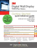
Image 5-2
Power input
4. Connect the male side of the power cord to the local power net.
Caution:
Ensure that the power net meets the power requirements of the projector.
For order number R9050130 and R90501301 100-120/200-240V 12/8A 50/60Hz
For order number R90501305 : 100-120/200-240V 16/8A 50/60Hz
W
ARNING
:
Do not attempt operation if the AC supply and cord are not within the speci
fi
ed voltage and power
range.
C
AUTION
:
Once the projector is switched to standby, the lamp cooling fans will continue to run for approx-
imately
fi
ve minutes to ensure that the projector and lamp have suf
fi
ciently cooled, at which point the fans
will automatically decrease to standby. To avoid thermal stress that can lead to premature lamp failure, never
unplug the power cord while the lamp cooling fans are running. Never unplug the power cord to power down
the projector,
fi
rst switch off the power switch and then unplug the power cord.
Fuses
The projector with order number R9050130 and R90501301 is protected with an automatic circuit breaker of 15 A and projector with
order number R90501305 is protected with an automatic circuit breaker of 20A. The circuit breaker is built in into the power switch.
Power input voltage versus light output (for R9050130 and R90501301)
When the input power is between 170V and 264V the maximum light output with 4 lamps can be reached.
In the low input power ranges the light output will be reduced to protect the projector.
When the input power is between 100V and 140V, 75% of the light output with 3 lamps can be reached.
When the input power is between 90V and 100V the light output is reduced to 62.5% with only 3 lamps.
36
R59770057 CLM HD8 15/03/2010
Summary of Contents for CLM HD8
Page 1: ...CLM HD8 User guide R9050130 R90501301 R90501305 R59770057 08 15 03 2010 ...
Page 14: ...1 Safety 10 R59770057 CLM HD8 15 03 2010 ...
Page 22: ...2 General 18 R59770057 CLM HD8 15 03 2010 ...
Page 34: ...3 Physical installation 30 R59770057 CLM HD8 15 03 2010 ...
Page 62: ...7 Start up of the adjustment mode 58 R59770057 CLM HD8 15 03 2010 ...
Page 72: ...8 Input menu 68 R59770057 CLM HD8 15 03 2010 ...
Page 114: ...10 Layout menu 110 R59770057 CLM HD8 15 03 2010 ...
Page 156: ...13 Projector control 152 R59770057 CLM HD8 15 03 2010 ...
Page 170: ...14 Service menu 166 R59770057 CLM HD8 15 03 2010 ...
Page 184: ...16 Servicing 180 R59770057 CLM HD8 15 03 2010 ...
Page 194: ...17 Projector covers removal and installation 190 R59770057 CLM HD8 15 03 2010 ...
Page 202: ...C DMX Chart 198 R59770057 CLM HD8 15 03 2010 ...
Page 208: ...D Specifications 204 R59770057 CLM HD8 15 03 2010 ...
Page 214: ...E Troubleshooting 210 R59770057 CLM HD8 15 03 2010 ...
Page 220: ...F Mounting optional Carry handle 216 R59770057 CLM HD8 15 03 2010 ...
Page 222: ...G Order info 218 R59770057 CLM HD8 15 03 2010 ...