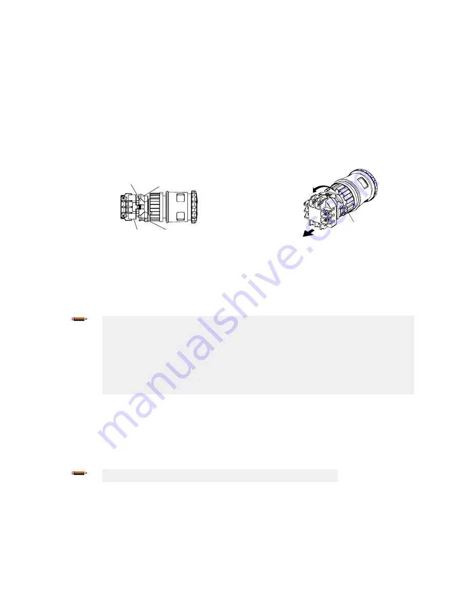
Remove the Contact Block
1. Arm (reset) the actuator (button). Do not attempt to remove the contact block while the actuator is latched (pushed), or the
switch may be damaged.
2. Grip the beveled surfaces at the corners of the yellow bayonet ring and pull the ring toward the contact block until the latch
pin clicks.
If the switch is not installed, place the contact block against the base of the index finger and grip the bayonet ring with the
thumb, index finger, and middle finger, then squeeze until the click is heard.
3. Rotate the contact block counterclockwise and pull out to remove the contact block. Do not use excessive force when
removing the contact block, or the switch may be damaged.
For illuminated pushbuttons, the LED lamp is built into the contact block. When removing the contact block, pull the contact
block straight to prevent damage to the LED lamp. Do not use excessive force or the LED lamp may be damaged and fail to
light.
When the contact block is removed, the monitor contact (normally open contact) is closed.
Bayonet Ring
Beveled Surface
Latch Pin
Contact Block
Pull
Contact Block
Panel Mounting
1. Remove the contact block and the M30 jam nut from the actuator and verify that the rubber gasket is in place.
2. Align the anti-rotation key on the bezel with the keyway (notch) in the panel.
3. Insert the actuator into the hole from the front of the panel, and tighten the M30 jam nut using wrench
SSA-EB1-LRW
or
SSA-EB1-LRTW
to a maximum torque of 2.5 N•m (1.8 ft-lbs).
Note:
•
The allowable panel thickness is 1 mm to 5 mm for SSA-EB1P… and 1 mm to 6 mm for SSA-
EB1M….
•
Banner recommends that the anti-rotation key/keyway is placed at the top of the hole (0° versus
90° or 180°) so the word “TOP” on the contact block and actuator is on the top so that the
terminal label is easier to read.
•
If using ESLP1-30/60-.. Plastic Emergency Stop legend, remove the anti-rotation projection on
the legend using pliers, and then install the legend onto the actuator before inserting it into the
hole.
Install the Contact Block
1. Arm (reset) the actuator (button). Do not attempt to install the contact block while the actuator is latched (pushed), or the
switch may be damaged.
2. Align the small ▼ mark on the edge of the actuator with the small ▲ mark on the yellow bayonet ring. The contact block
(TOP LOCK) should be turned approximately 45° counterclockwise from the anti-rotation key/keyway on the bezel.
3. Hold the black contact block (not the yellow bayonet ring), and slide the contact block onto the actuator. Push until the
actuator is fully inserted into the contact block (the bayonet ring will compress and motion will stop).
Note:
If not installed on a panel, press on the actuator’s bezel (not the button).
4. Turn the contact block clockwise until the yellow bayonet ring pops into position and clicks.
When properly seated, the contact block cannot be turned or pulled.
SSA-EB Series Emergency Stop Push Button
P/N 194992 Rev. D
www.bannerengineering.com - Tel: + 1 888 373 6767
3


