


4 Specifications
4.1 General Specifications
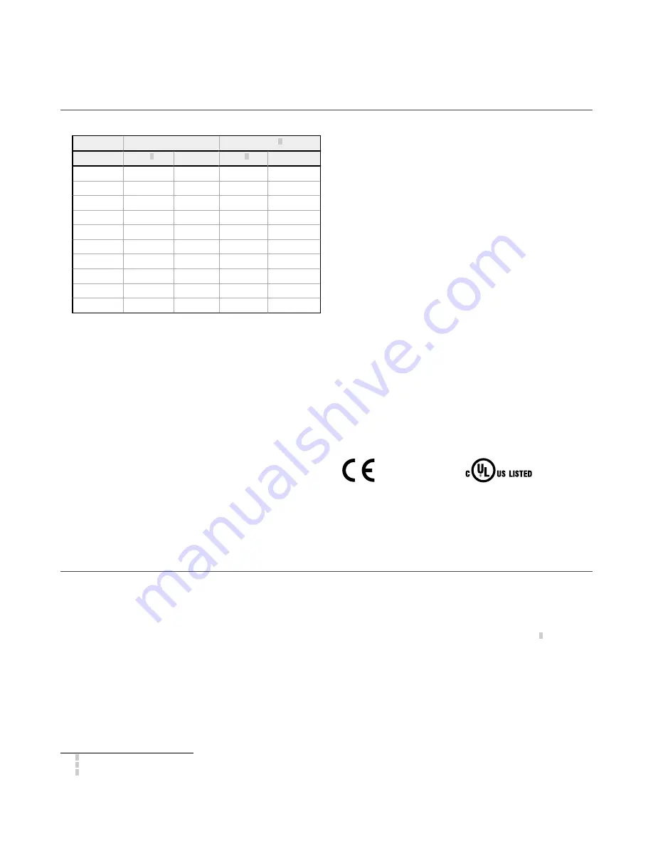
Supply Current (mA)
Emitter
Receiver2
Length
Max3
Typical
Max3
Typical
350
30
25
115
72
420
30
25
117
74
630
30
25
124
80
910
31
26
134
89
1050
31
26
139
93
1190
31
26
144
97
1260
32
26
146
99
1330
32
26
149
101
1540
32
27
156
108
1820
32
27
166
116
Resolution
23 mm
Effective Aperture Angle (EAA)
Meets Type 4 requirements per IEC 61496-2, Section 5.2.9
Enclosure
Extruded aluminum housing with yellow polyester powder finish
standard and well-sealed, rugged die-cast zinc end caps, acrylic lens
cover
Mounting Hardware
All mounting hardware is ordered separately. Models longer than 910
mm should use an additional center-mount bracket for support.
Mounting brackets are 8-gauge cold-rolled steel, black zinc finish.
Cables and Connections
See
Safety Rating
Type 4 per IEC 61496-1, -2
Category 4 PL e per EN ISO13849-1
SIL3 per IEC 61508; SIL CL3 per IEC 62061
PFHd: 1.30 × 10
-10
Proof Test Interval: 20 years
Supply Voltage at the Device
24 V dc ±15% (use a SELV-rated power supply according to EN IEC
60950).
The external voltage supply must be capable of buffering brief mains
interruptions of 20 ms, as specified in IEC/EN 60204-1.
Residual Ripple
±10% maximum
Short Circuit Protection
All inputs and outputs are protected from short circuits to +24 V dc or
dc common
Electrical Safety Class
III (per IEC 61140: 1997)
Operating Range
0.1m to 8 m (4 in. to 26.2 ft) — Range decreases with use of mirrors
and/or lens shields:
•
Lens shields — approx 10% less range per shield
•
Glass-surface mirrors — approx 8% less range per mirror
See the specific mirror datasheet for more information.
Operating Conditions
–20 °C to +55 °C (–4 °F to +131°F)
95% maximum relative humidity (non-condensing)
Environmental Rating
IEC IP65/IEC IP67
Shock and Vibration
Components have passed vibration and shock tests according to IEC
61496-1. This includes vibration (10 cycles) of 10-55 Hz at 0.35 mm
(0.014 in) single amplitude (0.70 mm peak-to-peak) and shock of 10 g
for 16 milliseconds (6,000 cycles).
Certifications
4.2 Receiver Specifications
Response Time
Dependent on the number of sensing beams; for the response time, see
on page 12
EDM Input (Available with 8-Conductor Models)
+24 V dc signals from external device contacts can be monitored (one-
channel or no monitoring) via the EDM terminal in the receiver.
High Signal: 10 to 30 V dc at 30 mA typical
Low Signal: 0 to 3 V dc
Recovery Time
Blocked to Clear (OSSDs turn On): Dependent on the number of beams
and whether the first beam (CH 1 synchronization beam) has been
blocked. For specific values, see
Output Signal Switching Devices (OSSDs)
Two redundant solid-state 24 V dc, 0.5 A max. sourcing OSSD
(Output Signal Switching Device) safety outputs (Use optional
interface solutions for ac or larger dc loads)
ON-State voltage: > Vin – 1.5 V dc
OFF-State voltage: 0 V dc typical, 1 V dc maximum (no load)
OFF-State, maximum allowed external voltage: 1.5 V dc
4
Maximum load capacitance: 1.0 µF
Maximum cable resistance to load: 5 ohms per wire
Maximum leakage current: 50 µA (with open 0 V)
OSSD test pulse width: 200 µs typical
OSSD test pulse period: 200 ms typical
Switching current: 0 A minimum; 0.5 A maximum (per OSSD)
Fault Output Switching Capacity (Available with 8-Conductor Models)
Current-sourcing (PNP) solid-state output, 24 V dc at 70 mA
maximum
2 Supply current exclusive of OSSD1 and OSSD2 loads (up to additional 0.5 A each) and Fault Output load (up to 0.070 A).
3 Maximum current occurs at a supply voltage of 20 V dc.
4
The maximum voltage allowed on the OSSDs in the OFF-state without a lockout occurring. This voltage may occur, for example, from the input structure of a safety relay module
connected to the EZ-SCREEN LS Basic OSSDs.
EZ-SCREEN
®
LS Basic Safety Light Screen
16
www.bannerengineering.com - Tel: 763.544.3164