


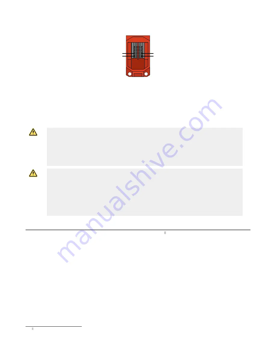
Figure 13. Safety Contacts at 21/22 and 41/42
41
42
33
34
13
14
21
22
CH2 (N.C.)
CH1 (N.C.)
To ensure the highest level of reliability (Control Reliable or Category 4, for example), wire the positively-driven safety contacts
(terminals 21/22 and 41/42) in a dual channel hookup to a safety module (for example, ES-FA-9AA), safety controller (for example,
XS/SC26 or SC10-2roe), or the safety related part of the machine control that complies with the required level of safety performance.
Two functions of the safety module or safety controller are:
1. To provide a means of monitoring the contacts of both safety switches for contact failure, and to prevent the machine from
restarting if either switch fails.
2. To provide a reset routine after re-arming/resetting the rope pull switch (returning the safety contacts to their closed
position). This prevents the controlled machinery from restarting by simply resetting the switch. This necessary reset
function is required by ANSI B11.0 and NFPA 79 machine safety standards.
WARNING:
•
Ensure the safety circuit integrity
•
The safety circuit integrity level is affected by the design and installation of the safety devices and the
means of interfacing with those devices.
•
Perform a risk assessment to determine the appropriate safety circuit integrity level or category to
ensure the expected risk reduction is achieved and all applicable regulations and standards are in
compliance (see ANSI B11.0 and ANSI B11.19, ISO 12100 and ISO13849-1 or the applicable
standards).
WARNING:
•
Connect two or more devices to the same safety module (controller) in series
•
Connecting devices in parallel defeats the switch contact monitoring ability of the module and creates an
unsafe condition that could result in serious injury or death.
•
Failure to test each device individually in this manner could result in undetected faults and create an
unsafe condition that could result in serious injury or death.
•
Connect the contacts of the corresponding pole of each switch in series. Never connect the contacts of
multiple switches in parallel. Individually actuate (engage) each device, then release (or re-arm) and
reset the safety module. This allows the module to check each switch and its wiring to detect faults.
Perform this check during the prescribed checkouts.
Maintenance/Checkout
At switch installation or replacement and at machine set up, a Designated Person
3
must test each switch for proper machine
shutdown response and check the switch(es) and installation for proper operation, physical damage, mounting (looseness), and
excessive environmental contamination. This must also take place on a periodic schedule determined by the user, based on the
severity of the operating environment and the frequency of switch actuations. This is generally determined by a risk assessment,
such as the one contained in ANSI B11.0. Adjust, repair, or replace components as needed. If inspection reveals contamination on
the switch, thoroughly clean the switch and eliminate the cause of the contamination. Replace the switch and/or appropriate
components when any parts or assemblies are damaged, broken, deformed, or badly worn; or if the electrical/mechanical
specifications (for the environment and operating conditions) have been exceeded. Always test the control system for proper
functioning under machine control conditions after performing maintenance, replacing the switch, or replacing any component of the
switch.
Additional items that should be included in the checkout and/or regularly scheduled maintenance of a rope pull system:
•
Check for proper rope tension and adjust as needed
•
Verify free operation (no binding) of the rope and proper tripping when the rope is pulled
•
Periodically lubricate the pulleys and other moving parts associated with the rope
•
Repair any loose or damaged hardware, worn/frayed rope (cable), missing red rope sheathing or flags/markers (if used)
•
Remove or clean off any contamination and eliminate its cause
3
A Designated Person is identified in writing by the employer as being appropriately trained to perform a specified checkout procedure.
Rope Pull Emergency Stop Switches
P/N 67709 Rev. C
www.bannerengineering.com - Tel: + 1 888 373 6767
7


