R55F Series Fiber-Optic Color Mark Sensors
A
B
C
Fiber
Clip
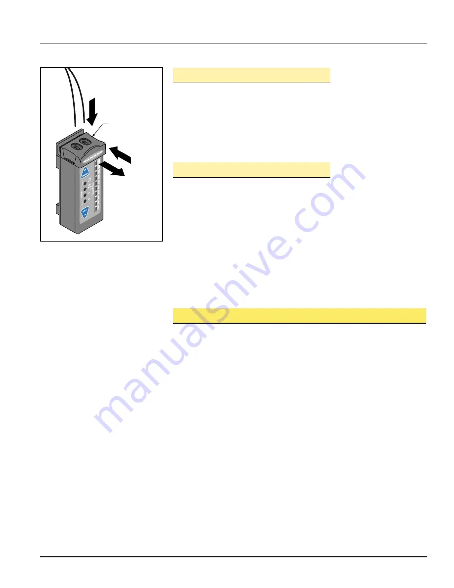
Figure 1. Installing fibers into the R55F
Series sensor
Plastic fibers
shown; procedure
is identical for
glass fibers
Glass Fiber Installation Procedure:
1) Check to see that a rubber o-ring is pre-installed on each fiber control end.
2) Slide the fiber clip to the open position (A).
3) Insert one fiber end into each port (B). Push firmly on the fiber ends to compress
the o-rings and align the grooves in the fiber ends with the slot in the fiber clip.
4) Slide the fiber clip back into place, locking the fibers into position (C).
Plastic Fiber Installation Procedure:
NOTE: R55F sensors accept 0.75, 1.0, and 1.5 mm (0.03", 0.04", and 0.06") core
diameter plastic fibers.
1) Cut the “control ends” (sensor ends) of the plastic fiber(s) to the desired length
per the procedure which accompanies the fiber assembly.
2) If not already done, separate bifurcated fibers by approximately 2" from the control
ends.
3) Slide the fiber clip to the open position (A).
4) Insert the fiber ends into each port and push them in as far as they will go (B).
5) Slide the fiber clip back into place, locking the fibers into position (C).
Fiber Optic Mounting Considerations
Mount the sensing end of the fiber optic assembly so that the light image is totally
contained within the boundaries of the color mark to be sensed. The light image is
made smaller by moving the sensing tip closer to the surface of the material to be
sensed.
When sensing marks on shiny (specular) materials, such as metal, plastic or glossy
paper, mount the sensing tip of the fiber at approximately 15° from perpendicular to
the material surface to minimize strong direct reflections.
Isolate the fiber mounting from vibration. Also, maintain mechanical stability of the
surface to be sensed (e.g., stabilize web flutter at the sensing point).
Buy: www.ValinOnline.com | Phone 844-385-3099 | Email: [email protected]


