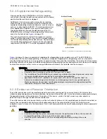
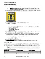
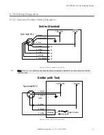
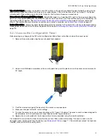
1. Select the proper test piece supplied with the receiver.
2. Verify that the System is in Run mode, the green Status indicator is on, all Zone indicators are green, and the amber
Status indicator is on.
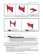
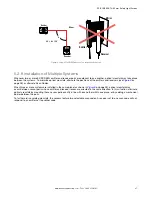
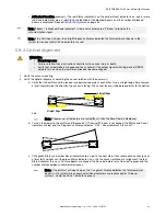
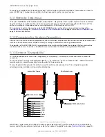
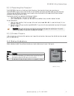
3. Pass the specified test piece through the defined area in three paths: near the emitter, near the receiver, and
midway between the emitter and receiver.
Receiver
Emitter
Test Piece
Figure 14. Trip Test
4. During each pass, while the test piece is interrupting the defined area, at least one Zone indicator must be red. The
red Zone indicator must change with the position of the test piece within the defined area.
• Trip Output Operation: The Status indicator must turn red and remain red for as long as the test piece
remains in the defined area. If not, the installation has failed the trip test.
• Latch Output Operation: The Status indicator must turn red and remain red. The amber Reset indicator must
remain on. If the Reset indicator begins to flash at any time while the test piece is interrupting the defined
area, the installation has failed the trip test.
If all Zone indicators turn green or fail to follow the position of the test piece while it is within the defined area, the
installation has failed the trip test. Check for correct sensor orientation, reflective surfaces, and unguarded areas
created due to the use of blanking. Do not continue until the situation is corrected.
When the test piece is removed from the defined area, in trip output operation, the Status indicator must be green
(or flash green of Reduced Resolution is enabled.) In Latch Output Operation, the Status indicator remains red until
a manual reset is performed (the amber Reset indicator flashes)..
WARNING:
• Trip test failure
• Using a system that has failed a trip test can result in serious bodily injury or death. If the
trip test has failed, the system might not stop dangerous machine motion when a person
or object enters the sensing field.
• Do not attempt to use the system if the system does not respond properly to the trip test.
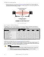
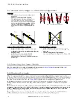
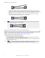
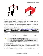
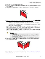
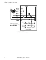
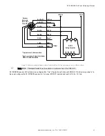
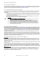
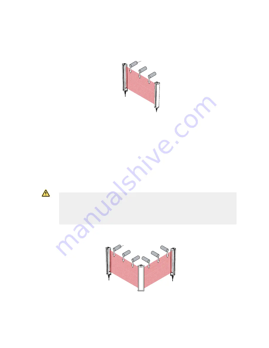
5. If mirrors are used in the application: Test the defined area on each leg of the sensing path (for example, emitter to
mirror, between mirror and receiver.
Receiver
Emitter
Test Piece
Mirror
Figure 15. Trip Test with Corner Mirror
6. If the EZ-SCREEN System passes all checks during the trip test, go on to
Electrical Connections to the Guarded
on page 38.
EZ-SCREEN
®
14/30 mm Safety Light Screen
www.bannerengineering.com - Tel: + 1 888 373 6767
37


