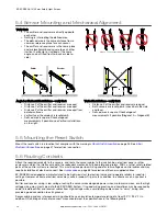
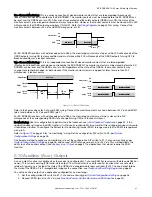
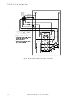
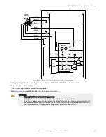
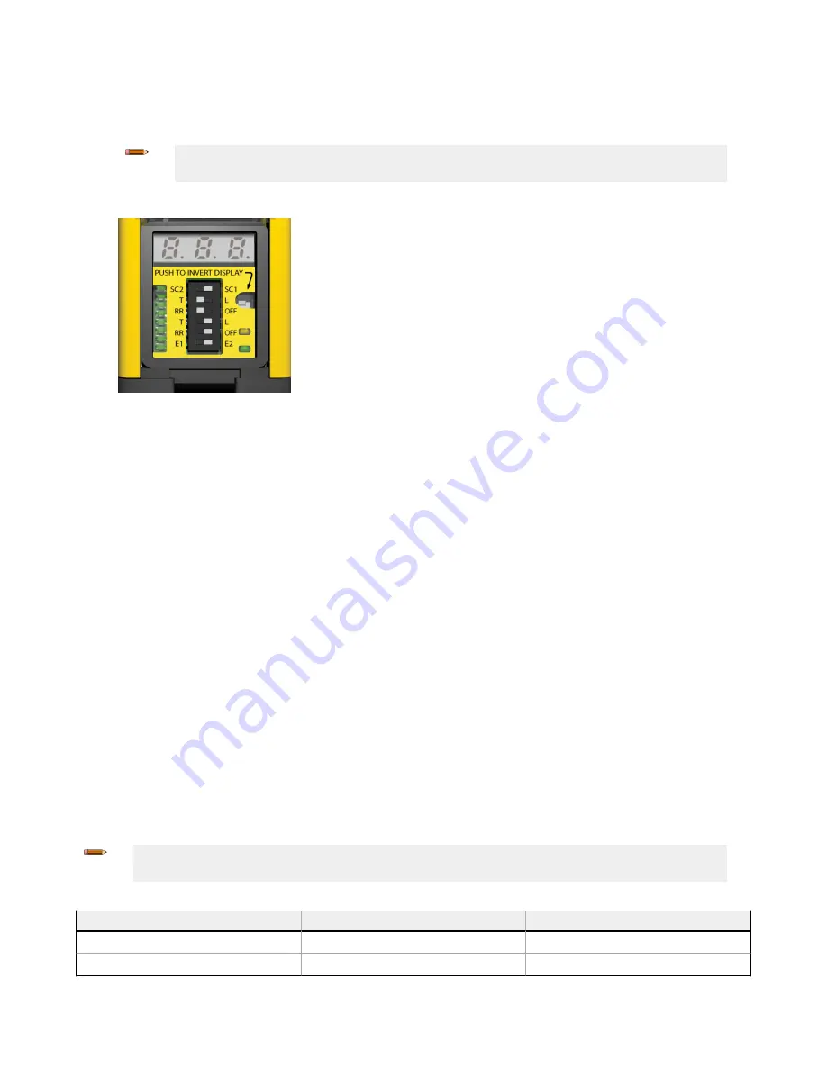
Configure Fixed Blanking
1. From normal operation or a power off condition, move the second and third DIP switches (the first RR and T/L) both
to the left (T and RR position).
Note: The fixed blanking process has a time limit of 10 minutes. If this time is exceeded, a lockout
occurs and the process must be started over.
2. Move the fourth and fifth DIP switches (the second RR and T/L) both to the right (L and OFF position). The first and
sixth DIP switches are not part of this process. Do not move them to match this image.
3. The receiver should now either be in a lockout condition or power is still off.
• If power is off: Apply power
• If the system is in a Lockout condition: Perform a valid reset sequence (close the reset switch for 0.25 to 2
seconds, then reopen the switch).
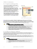
A fixed blanking configuration is indicated by:
• Display alternates between “PFA” and the number of blocked beams (“0” if all beams are clear). (PFA =
Program Fixed Blanking Active)
• Zone indicators are active
• Amber/yellow Reset indicator is off
• Red Status indicator is on
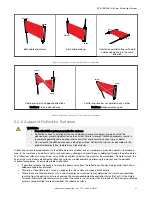
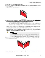
4. Position the object(s) to be blanked.
When the beams are blocked, the 7-segment display alternates between “PFA” and the number of blocked beams.
The zone indicators remain active and denote the location of blocked beams.
5. To teach the blanked beams, re-configure DIP switches for normal operation. Verify that only the objects to be
blanked are interrupting the defined area. A lockout occurs if an object is moved or removed after teaching.
The receiver indicates:
• Display: PFC on (PFC = Program Fixed Blanking Complete)
• Zone indicators flash the approximate location of fixed blanked area programmed
• Reset indicator single-flashing amber/yellow
• Status indicator single-flashing red
6. Perform a valid reset sequence or cycle the power.
7. To disable fixed blanking, follow this same procedure, but remove all objects not to be blanked at step 4.
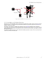
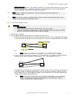
5.8.7 Trip Test
After optimizing the optical alignment, perform the trip test to verify the detection capability of the EZ-SCREEN System. This
test will also verify correct sensor orientation and identify optical short circuits. Once the installation has passed the trip
test, the safety outputs may be connected and the commissioning checkout may be performed (initial installations only).
Note: Cascaded systems—To test a cascaded system, each light screen must be tested individually, while
monitoring the status indicator on the first receiver in the cascade.
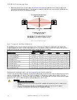
Table 3: Appropriate Test Pieces for the Trip Test
Reduced Resolution
14 mm Resolution Models
30 mm Resolution Models
OFF
14 mm (0.55 in) dia. Model STP-13
30 mm (1.18 in) dia. Model STP-14
ON (2-beam)
30 mm (1.18 in) dia. Model STP-14
60 mm (2.36 in) dia. Model STP-15
EZ-SCREEN
®
14/30 mm Safety Light Screen
36
www.bannerengineering.com - Tel: + 1 888 373 6767


