


ANSI NFPA 79 Electrical Standard for Industrial Machinery
Contact: National Fire Protection Association, 1 Batterymarch Park, P.O. Box 9101, Quincy, MA 02269-9101, Tel.:
800-344-3555
ANSI/RIA R15.06 Safety Requirements for Industrial Robots and Robot Systems
Contact: Robotic Industries Association, 900 Victors Way, P.O. Box 3724, Ann Arbor, MI 48106, Tel.: 734-994-6088
Applicable International Standards
ISO 12100-1 & -2 (EN 292-1 & -2) Safety of Machinery – Basic Concepts, General Principles for Design
ISO 13849-1 Safety-Related Parts of Control Systems
ISO 13850 (EN 418) Emergency Stop Devices, Functional Aspects – Principles for Design
IEC 60204-1 Electrical Equipment of Machines Part 1: General Requirements
Contact: Global Engineering Documents, 15 Inverness Way East, Englewood, CO 80112-5704, Tel.: 800-854- 7179
Overview
An Emergency Stop Safety Module is used to increase the control reliability of an
emergency stop circuit. As shown in the hookup drawings, the models ES-
FA-9AA and ES-FA-11AA E-Stop Safety Modules are designed to monitor a 1-
channel or 2-channel E-stop switch. A 2-channel E-stop switch has two
electrically isolated contacts.
WARNING: Risk Assessment
The level of safety circuit integrity can be greatly affected
by the design and installation of the safety devices and the
means of interfacing of those devices. A risk assessment
must be performed to determine the appropriate level
of safety circuit integrity to ensure the expected risk
reduction is achieved and all relevant regulations and
standards are complied with.
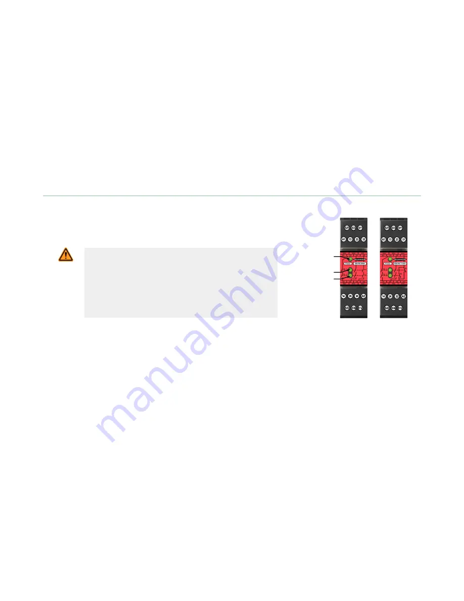
ES-FA-9AA
ES-FA-11AA
Power ON LED
Channel 1
Active LED
Channel 2
Active LED
Figure 1. Features and Terminals
Safety Circuit Integrity and ISO 13849-1 (EN954-1) Safety Circuit Principles
Safety circuits involve the safety-related functions of a machine that minimize the level of risk of harm. These safety-
related functions can prevent initiation, or they can stop or remove a hazard. The failure of a safety-related function or its
associated safety circuit usually results in an increased risk of harm.
The integrity of a safety circuit depends on several factors, including fault tolerance, risk reduction, reliable and well-tried
components, well-tried safety principles, and other design considerations.
Depending on the level of risk associated with the machine or its operation, an appropriate level of safety circuit integrity
(performance) must be incorporated into its design. Standards that detail safety performance levels include ANSI B11.19
Performance Criteria for Safeguarding and ISO 13849-1 Safety-Related Parts of a Control System.
Safety Circuit Integrity Levels
Safety circuits in International and European standards have been segmented into categories, depending on their ability to
maintain their integrity in the event of a failure. The most recognized standard that details safety circuit integrity levels is
ISO 13849-1 (EN954-1), which establishes five levels: Categories B, 1, 2, 3, and the most stringent, Category 4.
In the United States, the typical level of safety circuit integrity has been called ”control reliability.” Control reliability
typically incorporates redundant control and self-checking circuitry and has been loosely equated to ISO 13849-1
Categories 3 and 4 (see CSA Z432 and ANSI B11.TR4).
If the requirements described by ISO 13849-1 (EN954-1) are to be implemented, a risk assessment must first be
performed to determine the appropriate category, in order to ensure that the expected risk reduction is achieved. This risk
assessment must also take into account national regulations, such as U.S. control reliability or European “C” level
standards, to ensure that the minimum level of performance that has been mandated is complied with.
ES-FA-9AA and ES-FA-11AA E-Stop Safety Module
2
www.bannerengineering.com - Tel: +1-763-544-3164
P/N 60606 Rev. G