background image


P/N 64154 rev. F


11 

D10 

Expert

 Dual Discrete Outputs

Banner Engineering Corp. 

• 

Minneapolis, MN U.S.A.

www.bannerengineering.com  •  Tel: 763.544.3164

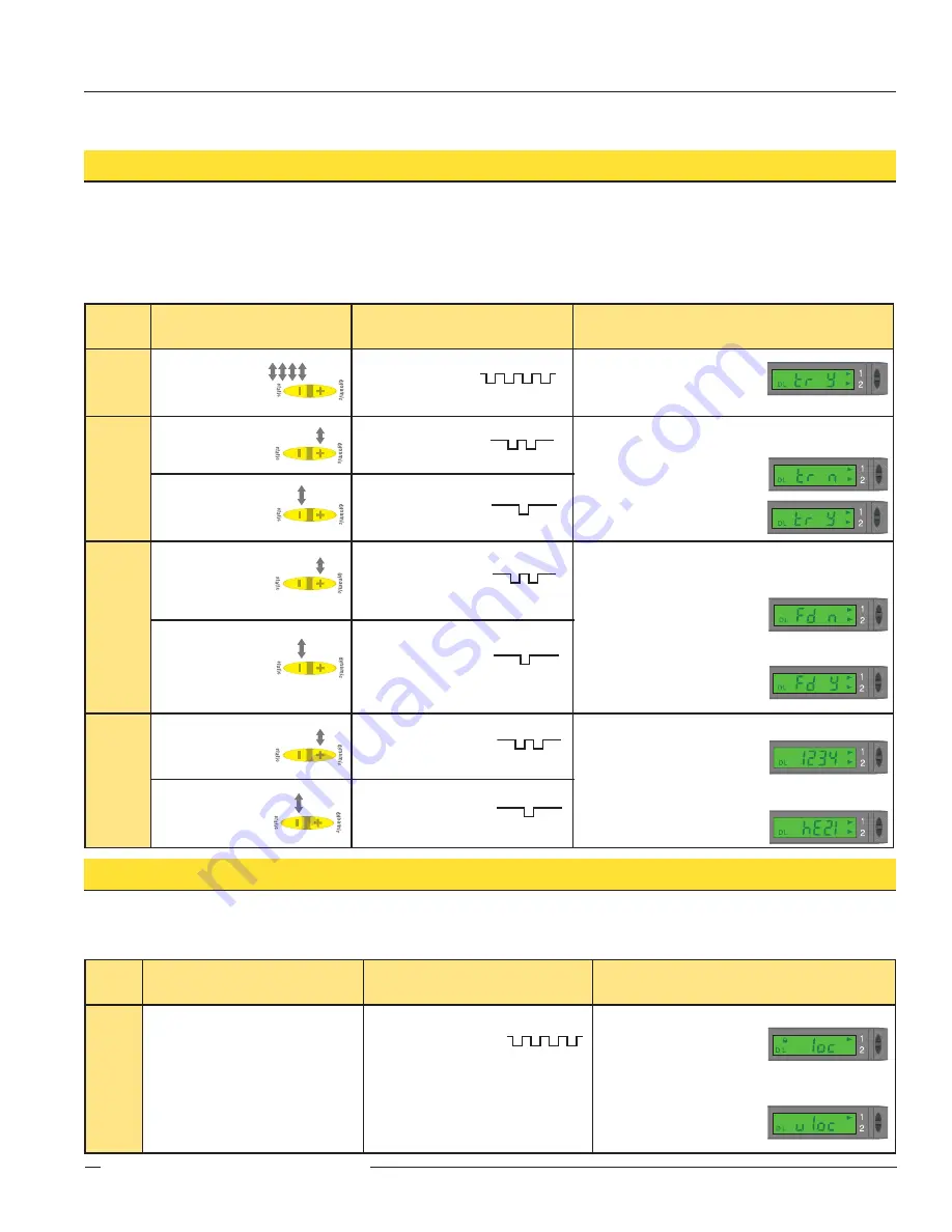
Advanced Setup

• Advanced adjustments to previously configured sensor display and operating parameters.


• Quad-click Static (-) or quad-pulse remote line before exiting “Power and Speed” settings to enter this mode.


• Click Dynamic (+) or double-pulse remote line to select an option.


• Click Static or single-pulse remote line to advance.


• Changes are updated instantly.

Push Button Lockout

• Prevents unwanted adjustments or tampering of the push buttons.


• Push buttons can be enabled or disabled only from the remote line and only during normal RUN mode.

Push Button

Remote 

0.04 sec. ≤ T ≤ 0.8 sec.

Result

Enable 

or 

Disable


Push 

Buttons

• Not available with


  push-button programming.

• From RUN mode, 


  quad-pulse the 
  remote line to toggle 
  between selections.

Push Buttons Disabled:


• Display flashes “

loc

” 

• Padlock icon appears


• Sensor remains in RUN mode


Push Buttons Enabled:


• Display flashes “

uloc

” 

• Padlock icon disappears


• Sensor remains in RUN mode

T

T

T

T

T

T

T

T

T

T

dynamic

static

dynamic

static

Push Button

Remote 

0.04 sec. ≤ T ≤ 0.8 sec.

Result

Enter


SETUP


Mode

• From “Power


  and Speed” 
  mode, quad-click  
  Static (-) button.

• From “Power


  and Speed” mode, 
  quad-click the 
  remote line.

•  Indicator Arrow Icons 


1 and 2 remain red

•   Display shows


“Tracking Enabled” option.

Track 

Enable

• Click Dynamic (+)


  to toggle 
  between selections.

• Double-pulse the


  remote line to toggle 
  between selections.

Sets output 2 identical to output 1


Tracking disabled:


• Display shows  “

tr n

” 


Tracking enabled:


• Display shows  “

tr y

• Click Static (-) to


  save selection and 
  advance to 

  “Factory Default.”

• Single-pulse the remote 


  line to save selection  
  and advance to 

  “Factory Default.”

Factory 

Default 

Settings

• Click Dynamic (+) 


  to toggle 
  between selections.

• Double-pulse the  


  remote line to 
  toggle between 
  selections.

Returns to factory default factory settings


Factory Default Settings 
Not Selected:


• Display shows  “

fd n

” 


Factory Default Settings 
Selected:


• Display shows  “

fd y

• Click Static (-) to


  advance to 

  “Display Orientation.”

• Single-pulse the


  remote line to 
  advance to 

  “Display Orientation.”

Display 

Orientation

• Click Dynamic (+)


  to toggle between 
  selections.

• Double-pulse the


  remote line to toggle 
  between selections.

Inverts display to read “upside-down”


Normal:


• For example: 1234


Inverted:


• For example:


  NOTE: Icons do not invert.

• Click Static (-) to


  return to 
  RUN mode.

• Single-pulse the 


  remote line to 
  return to RUN mode.

1234

T

T

T

T

T

T

T

T

T

T

T

T

T

T

T

T

T

T

T

T

T

T

T

T

T

T

T

T

T

T

T

T

T

T

T

T

T

T

T

T

T

T

T

T

T

T

T

T

T

T

T

T

T

T

T

T

T

T

T

T

T

T

T

T

T

T

T

T

T

T

dynamic

static

dynamic

static

dynamic

static

dynamic

static

dynamic

static

dynamic

static

dynamic

static

Summary of Contents for D10 Expert

Page 1: ... m or 9 m 6 5 or 30 cable or integral Pico style quick disconnect Sleek ultra slim 10 mm housing mounts to a standard 35 mm DIN rail U S Patent 5 808 296 9 m 30 cables are available by adding suffix W 30 to the model number of any cabled sensor e g D10DNFP W 30 A model with a QD connector requires a mating cable see page 14 WARNING Not To Be Used for Personnel Protection Never use these products a...

Page 2: ... or when the target is absent OFF Delay Timing Selection Programmable OFF delay pulse stretcher 0 2 5 10 15 20 30 40 60 80 or 100 milliseconds Display Selection Discrete Output Raw signal value or excess signal Power Level Speed Selection Super High Speed SHS High Speed HS High Power HP Super High Power SHP Response 50 µs 200 µs 1 ms 2 5 ms Repeatability 25 µs 50 µs 75 µs 100 µs Maximum Range Fibe...

Page 3: ...ess and hold the Static button for 2 seconds to cancel out of SETUP mode press and hold both the Static and Dynamic buttons for 2 seconds Output 2 The setpoint s for each output can be set independently of one another see Super High Speed Operation However the functional range available for output 2 is dictated by the automatic power and gain settings established for output 1 Whenever output 1 is ...

Page 4: ...nual Adjust page 9 Static TEACH is the traditional setup method used when two conditions can be presented by the user The sensor locates a single sensing threshold the switchpoint midway between the two taught conditions with the Output ON condition on one side and the Output OFF condition on the other see Figure 2 The first condition taught is the ON condition The Output ON and OFF conditions can...

Page 5: ...ess and hold Dynamic button Hold remote line low to ground Display flashes dyn Arrow icon turns red TEACH Sensing Conditions Present Output ON OFF conditions while continuing to hold Dynamic button Present Output ON OFF conditions while continuing to hold remote line low to ground Return to RUN Mode Release Dynamic button Release remote line switch TEACH conditions acceptable Display flashes pass ...

Page 6: ... extends 200 counts above and below the taught condition including 100 counts hysteresis All other conditions lighter or darker result in OFF output Sensing window sensitivity is adjustable using and buttons see Manual Adjust page 9 Window SET is most useful when a product may not always appear in the same place or when other signals may appear Window SET designates a sensing window with the Outpu...

Page 7: ...st Sensor positions threshold slightly below the presented condition Sensor positions threshold slightly above the presented condition Darkest no signal Darkest no signal Most Light saturated signal Most Light saturated signal Darkest no signal Most Light saturated signal Condition Presented Output OFF Output OFF Output ON Output OFF Output ON Condition Presented Output OFF Output ON Condition Pre...

Page 8: ...ter 60 seconds sensor returns to RUN mode Arrow icon turns green without changing settings T T T T T T T T T T T T T T T T T T T T T T T T T T T T T T T T T T T T T T T T T T T T T T T T T T T T T T T T Push Button Remote dynamic static dynamic static dynamic static dynamic static dynamic static dynamic static Mode Threshold Offset counts above taught signal value Super High Speed 30 High Speed 22...

Page 9: ...ing Threshold Fine tunes sensing sensitivity Press to increase press to decrease Sensing Window Adjusts sensing window size tolerance for the single point target condition Press to increase press to decrease Push Button Remote Result Manual Adjust Click to increase or click to decrease Not available with remote programming Display briefly flashes the threshold setpoint value as it is being changed...

Page 10: ...ouble pulse the remote line to toggle between selections OFF No OFF Delay t 0 Clock icon OFF 2 to 100 ms OFF Delay t 2 t 5 t 10 t 15 t 20 t 30 t 40 t 60 t 80 or t100 Clock icon ON Click Static to save selection and advance to Display Single pulse the remote line to save selection and advance to Display Select Display Parameters Click Dynamic to toggle between selections Double pulse the remote lin...

Page 11: ...mode quad click the remote line Indicator Arrow Icons 1 and 2 remain red Display shows Tracking Enabled option Track Enable Click Dynamic to toggle between selections Double pulse the remote line to toggle between selections Sets output 2 identical to output 1 Tracking disabled Display shows tr n Tracking enabled Display shows tr y Click Static to save selection and advance to Factory Default Sing...

Page 12: ...or 2 PNP depending on model Output Rating 150 mA maximum load OFF state leakage current 10 µA at 24V dc ON state saturation voltage NPN 1 5V at 150 mA load PNP 2 5V at 150 mA load Output Protection Circuitry Protected against false pulse on power up and continuous short circuit Output Response Time Programmable 50 microseconds 200 microseconds 1 millisecond 2 5 milliseconds NOTE 1 second delay on ...

Page 13: ...13 deep ø4 4 mm 0 18 thru 2x 3 5 mm 0 14 5 0 mm 0 20 8 6 mm 0 34 25 4 mm 1 00 16 0 mm 0 63 2 x ø3 3 mm 0 13 2x ø3 2 mm 0 13 2 5 mm 0 10 5 0 mm 0 20 M3 Hardware included Lock Washer 2 Flat Washer 2 Screws 2 Hex Nuts 2 Included Bracket Dimensions 61 3 mm 2 42 68 1 mm 2 68 Plastic Fiber Emitter Port Plastic Fiber Receiver Port 10 5 0 2 mm typ 0 41 Mounting Bracket included Slides Up to Release Fibers...

Page 14: ...Temperature 40 to 90 C 40 to 194 F Voltage Rating 30V ac 36V dc Style Model Length Dimensions Pin out 6 Pin Straight PKG6Z 2 2 m 6 5 PKG6Z 9 9 m 30 6 Pin Right angle PKW6Z 2 2 m 6 5 PKW6Z 9 9 m 30 28 mm max 1 1 ø 10 mm max 0 4 20 mm 0 8 25 mm max 1 0 ø12 mm max 0 5 Brown Wire Gray Wire Pink Wire Blue Wire Black Wire White Wire Hookups NPN Output Models PNP Output Models bu 12 24V dc 1 2 Teach Gate...

Page 15: ...P N 64154 rev F 15 D10 Expert Dual Discrete Outputs Banner Engineering Corp Minneapolis MN U S A www bannerengineering com Tel 763 544 3164 ...

Page 16: ...s its products to be free from defects for one year Banner Engineering Corp will repair or replace free of charge any product of its manufacture found to be defective at the time it is returned to the factory during the warranty period This warranty does not cover damage or liability for the improper application of Banner products This warranty is in lieu of any other warranty either expressed or ...

Reviews: