Advanced Configuration
Use the following procedures for a more advanced configuration of the ABR. Advanced configuration requires Barcode Manager software. For
complete configuration instructions, refer to the Instruction Manual at
. Search for p/n 207634 to view the Instruc-
tion Manual.
Install
Barcode Manager
Administrative rights are required to install the Barcode Manager software.
Important: Install Barcode Manager on a Windows
®
XP, 7, 8, or 10
7
computer. Barcode Manager does not currently sup-
port Windows Embedded (often used in industrial PCs and/or PLCs).
1. Download the latest version of Barcode Manager from
2. Navigate to and open the downloaded file.
3. Run
Barcode Manager_Setup.exe
to access the installation screen.
4. Follow the onscreen installation procedure.
After the installation is complete, the Barcode Manager entry is created under Start > Programs > Banner Engineering. A desktop icon
is also created.
Ethernet Device Discovery
The following configuration procedure assumes that a laptop computer running Barcode Manager is connected to a factory default reader
through the Ethernet port.
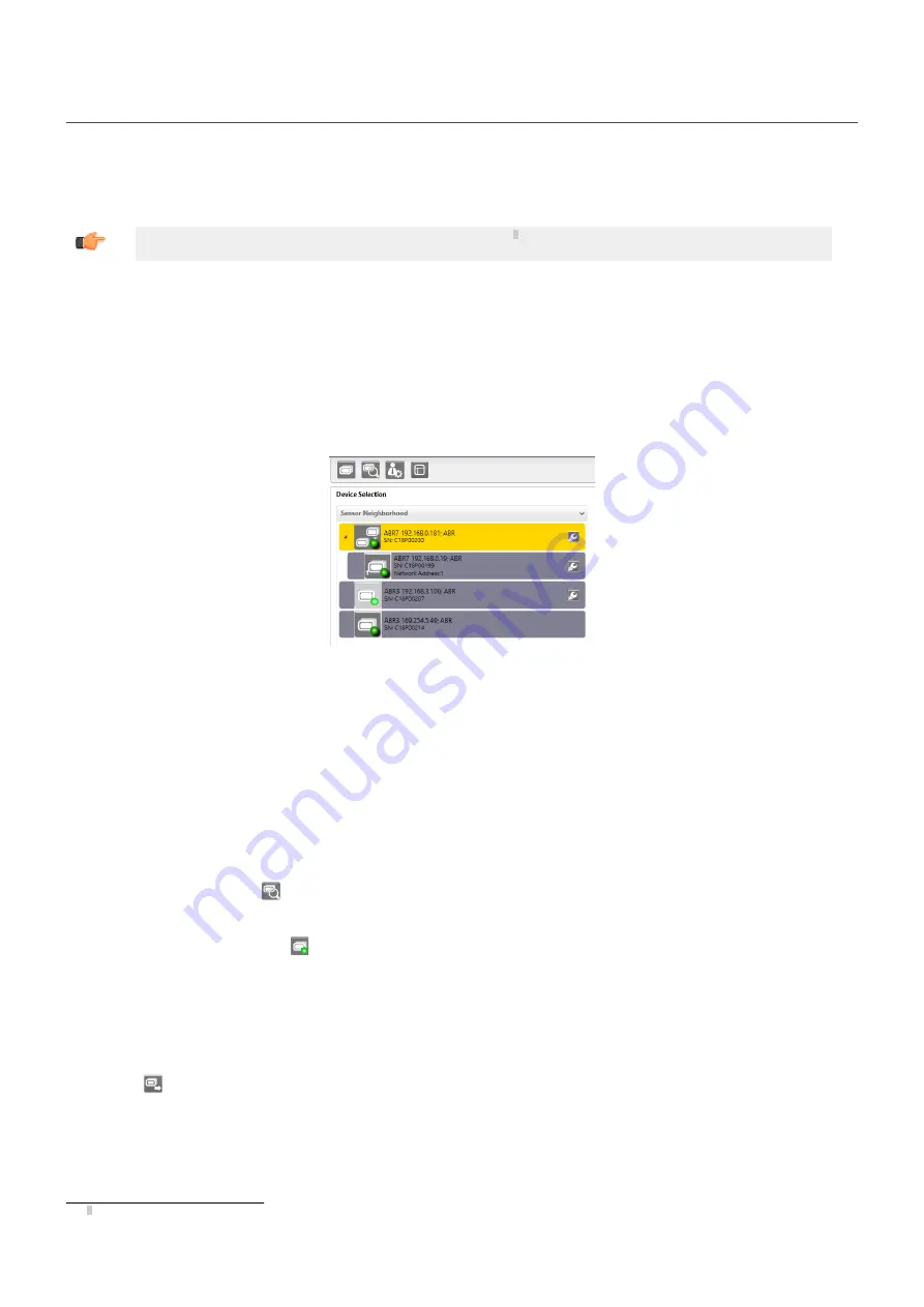
The Barcode Manager user interface opens and displays a list of all the devices belonging to the Local Area Network (LAN).
Figure 9. Device Discovery
The Barcode Manager discovery feature also shows devices not belonging to the LAN and displays them in light gray (see
The following is an example configuration for Windows
®
operating system version 7, 8, or 10.
1. Confirm the network connections. Changing the Local Area Connection (LAN) properties of the programming computer to be compat-
ible with the ABR device on the network may be required for connection.
a) Click the Start button, then on the Start menu, click Control Panel or search for Control Panel.
b) In Control Panel, click Network and Internet, then click Network and Sharing Center, and then click Change adapter settings.
c) Right-click on the connection that you want to change, then click Properties.
If you are prompted for an administrator password or confirmation, enter the password or provide confirmation.
d) In the connection properties, click Internet Protocol Version 4 (TCP/IPv4), and then click Properties.
e) In the Internet Protocol (TCP/IPv4) Properties, select Use the following IP address.
f)
Make sure that the IP address is 192.168.3.1, and the subnet mask is 255.255.255.0.
The IP address must be compatible with the default device address 192.168.3.100.
2. As an alternate method, change the IP address of the device.
3.
In Barcode Manager, click
Find Devices.
The device displays in Sensor Neighborhood with a dark gray icon, meaning it is now part of the LAN and can be configured. The new
IP address also displays.
4.
Double-click or drag the device
icon into the Selected Device Information Area.
Details about the device display in this area.
After device discovery, configure your device through Barcode Manager. Go to
Automatic Setup
To begin configuration, the reader must be correctly mounted at the correct reading distance for your application so that its Field of View cov-
ers the application reading area.
1.
Click
Open Device Configuration. The Open Device Configuration window opens showing the list of configurations (jobs) currently
saved on the device. For new devices, the only saved configuration is the Default configuration.
2. Click OK. The device enters continuous mode and begins acquiring images.
3. Place the application code in front of the reader at the correct application reading distance.
4. If needed, focus the reader on the code.
7 Microsoft and Windows are registered trademarks of Microsoft Corporation in the United States and/or other countries.
ABR 7000
P/N 207633 Rev. A
www.bannerengineering.com - Tel: +1-763-544-3164
5


