background image

C O N N E C T   W I T H   C O N F I D E N C E

4

222 SERIES

333 & 444 SERIES

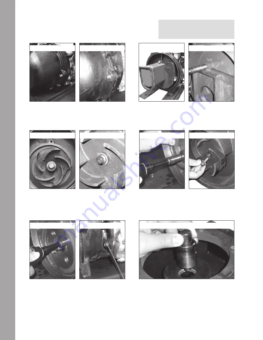
DISASSEMBLY INSTRUCTIONS:

Remove the (6) bolts (222: 12715A, 333/444: V20011SS) and lock 

washers (222: V10118, 333/444: V20018) that hold the pump body 

assembly onto the rear bracket. Remove the body from the remaining 

pump assembly.

2

1

3

4

Remove the (4) bolts (222: 12715A, 333/444: 18027) and lock 

washers (222: 12901, 333/444: V20018) that hold the rear bracket 

to the drive unit. With the 4 bolts removed, the rear bracket can be 

removed from the drive unit. With the pump completely disas-

sembled, clean all of the reusable parts thoroughly removing any 

traces of gasket material with a scraper or wire brush. Remove any 

corrosion on the sealing surfaces of the pump components.

5

222 SERIES

333 & 444 SERIES

222 SERIES

333 & 444 SERIES

222 SERIES

333 & 444 SERIES

222 SERIES

333 & 444 SERIES

NOTE: 

If bracket shims have been installed from the factory,  

the same number of shims will need to be reinstalled

Remove the impeller bolt (222: 12765A, 333/444: 16765) from the 

impeller (222: 15772, 333/444: 16772). Remove the impeller bolt 

gasket from the impeller.

Remove the cup seal half from the rear bracket. This may be done 

by using a round object such as a socket and tapping it with a 

hammer as shown in the photo. If necessary, remove the inlet and 

outlet flanges, the flange gaskets by removal of the flange screws 

and lock washers.

6

5

222, 333 & 444 SERIES

Remove the (3) bolts (222: 12715A, 333/444: V20011SS) and lock 

washers (222: V10118, 333/444: V20018) holding the volute to the 

rear bracket. Remove the volute (222: 15702, 333/444: 16702) from 

the remaining pump assembly. Replace checkvalve if needed.

Screw the supplied (222: 7/16″-14, 333/444: 9/16″-12) hex head cap 

screw (16099) into the threaded hole in the impeller. As it tightens, 

the impeller will pull off the shaft. Remove the hex head cap screw 

once the impeller is removed. If reusing the pump impeller, remove 

the primary ring of the seal (222: 12733V, 333/444: 16713) and the 

impeller key (222: 12902A, 333/444: 16901).

Summary of Contents for 222 Series

Page 1: ...NTRIFUGAL PUMPS INSTRUCTION MANUAL BANJO CORPORATION A Unit of IDEX Corporation 150 Banjo Drive Crawfordsville IN 47933 U S A banjocorp com Telephone 765 362 7367 B A N J O C O R P C O M 2 222 SERIES...

Page 2: ...is equipped from the factory with a 4 inlet flange the pump should be plumbed with a 4 inlet line If the pump is equipped from the factory with a 3 inlet flange the pump should be plumbed with a 3 inl...

Page 3: ...scharge 2 NPT Port Size Suction 3 NPT Discharge 3 NPT Port Size Suction 4 NPT Discharge 4 NPT PERFORMANCE 0 5 10 15 20 25 30 35 40 45 50 205 175 134 97 69 29 0 FLOW GPM 0 20 40 60 80 100 120 Pressure...

Page 4: ...ry the same number of shims will need to be reinstalled Remove the impeller bolt 222 12765A 333 444 16765 from the impeller 222 15772 333 444 16772 Remove the impeller bolt gasket from the impeller Re...

Page 5: ...22 or a 1 5 8 12 point socket 333 444 to give even pressure on the metal flange of the seal housing during installation The seal should be pressed into its bore Do not strike the seal with a sharp blo...

Page 6: ...th the impeller boltgasket or O ring and the impeller bolt Tighten the impeller bolt to 12 ft lb 222 or 45 ft lb 333 444 The impeller bolt will pull the impeller into its final position on the drive u...

Page 7: ...Banjo pump will not prime while operating below 1750 RPM g Verify correct pump rotation if an electric motor or hydraulic motor is being used A counter clockwise rotation right hand rotation is requir...

Page 8: ...ive unit is properly sized for the pump and its application 7 GRINDING TICKING OR WHIRRING SOUND DURING PUMP OPERATION THAT IS UNUSUAL a Verify that the impeller bolt has not loosened letting the impe...

Page 9: ...with continuity between its terminals as shown Wire Color IGN Bl GND G BAT W LO Bl Y ST Bl W Switch Position OFF ON START GX630 GX660 GX690 Technical Manual 2009 American Honda Motor Co Inc All Rights...

Page 10: ...mplified overview of required components Additional information regarding manufacturers of CARB certified fuel system components can be found at http www arb ca gov msprog offroad sore sorecomponent s...

Reviews: