background image

The cartridge, stylus, and

tonearm

3.1 MMC: Micro Moving Cross

As mentioned above, when a wire is
moved through a magnetic field, a
current is generated in a wire that is
proportional to the velocity of the
movement. In order to increase the
output, the wire can be wrapped into a
coil, e

ectively lengthening the piece

of wire moving through the field. Most
phono cartridges make use of this
behaviour by using the movement of
the stylus to either:

move tiny magnets that are
placed near coils of wire (a

Moving Magnet

or

MM

design)

or

move tiny coils of wire that are
placed near very strong magnets
(a

Moving Coil

or

MC

design)

In either system, there is a

relative

physical movement that is used to
generate the electrical signal from the
cartridge. There are advantages and
disadvantages associated with both of
these systems, however, they will not
be discussed here.

There is a third, less common design
called a

Moving Iron

(or

variable-reluctance

1

) system, which

can be thought of as a variant of the
Moving Magnet principle. In this
design, the magnet and the coils
remain stationary, and the stylus
moves a small piece of iron instead.
That iron is placed between the north
and south poles of the magnet so that,
when it moves, it modulates (or varies)
the magnetic field. As the magnetic
field modulates, it moves relative to
the coils, and an electrical signal is
generated. One of the first examples of
this kind of pickup was the Western
Electric 4A reproducer made in 1925.

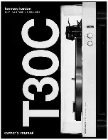
Figure 3.1: Figures from Rørbaek Mad-

sen’s 1963 patent for a Stereophonic

Transducer Cartridge.

In 1963, Erik Rørbaek Madsen of Bang
& Olufsen filed a patent for a cartridge
based on the Moving Iron principle. In
it, a cross made of Mu-metal is
mounted on the stylus. Each arm of
the cross is aligned with the end of a
small rod called a “pole piece”
(because it was attached to the pole of
a magnet on the opposite end). The
cross is mounted diagonally, so the
individual movements of the left and
right channels on the groove cause the
arms of the cross to move accordingly.
For a left-channel signal, the bottom
left and top right cross arms move in
opposite directions - one forwards and
one backwards. For a right-channel
signal, the bottom right and top left
arms move instead. The two coils that
generate the current for each audio
channel are wired in a push-pull
relationship.

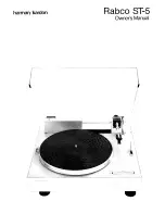
Figure 3.2: Erik Rørbaek Madsen ex-

plaining the MMC concept.

There are a number of advantages to
this system over the MM and MC
designs. Many of these are described
in the original 1963 patent, as follows:

“The channel separation is very
good and induction of cross talk
from one channel to the other is
minimized because cross talk
components are in phase in
opposing coils.”

“The moving mass which only
comprises the armature and the
stylus arm can be made very low
which results in good frequency
response.”

“Hum pick-up is very low due to
the balanced coil construction”

“... the shielding e

ect of the

magnetic housing ... provides a
completely closed magnetic
circuit which in addition to
shielding the coil from external
fields prevents attraction to steel
turntables.”

Finally, (although this is not
mentioned in the patent) the

1

reluctance is the magnetic equivalent of electrical resistance

2

Sound Recording Handbook”, ed. Glen Ballou

7

Summary of Contents for Beogram 4000c

Page 1: ...Beogram 4000c Technical Sound Guide Bang Olufsen A S This manual is for information purposes only and is not legally binding November 27 2020...

Page 2: ...ross 7 3 2 Signal Levels 8 3 3 Tip shape 10 3 4 Bonded vs Nude 12 3 5 Tracking force 12 3 6 E ective Tip Mass 12 3 7 Compliance 13 3 8 Soundsmith SMMC20CL 13 4 Audio Specifications 14 4 0 1 Magnitude...

Page 3: ...Emil Berliner was awarded a patent for a sound recording and reproducing system that was based on a groove in a rotating disc rather than Edison s cylinder the original version of the system that we k...

Page 4: ...are the same at Time 0 ms However it is also evident that when this is true they have very di erent amplitudes in fact the amplitude would have to double for every halving of frequency a drop of 1 oc...

Page 5: ...ns of the RIAA equalisation filter define the transition points as time constants instead of frequencies So instead of 50 Hz 500 Hz and 2122 Hz as shown in the response plots the points are listed as...

Page 6: ...down left up right for example This means that signals that are identical in both channels move the stylus laterally exactly as in earlier monophonic discs 4 Figure 2 10 An over simplified depic tion...

Page 7: ...eophonic Transducer Cartridge In 1963 Erik R rbaek Madsen of Bang Olufsen filed a patent for a cartridge based on the Moving Iron principle In it a cross made of Mu metal is mounted on the stylus Each...

Page 8: ...be encoded without incurring additional distortion that is inherent in the encoding system itself is when the maximum or minimum value in the audio signal reaches the highest possible signal value of...

Page 9: ...here is a relationship between the total playing time of a vinyl disc and the modulation velocity In order to have 20 minutes of music on a 12 LP spinning at 33 1 3 RPM then it the standard method was...

Page 10: ...here are a number of options when choosing the shape of the playback stylus 3 3 Tip shape The earliest styli were the needles that were used on 78 RPM gramophone players These were typically made from...

Page 11: ...k deeper into the groove making it more di cult for it to move independently on the two audio channels The second is that the point of contact between the stylus and the vinyl becomes smaller which ca...

Page 12: ...pin which is in turn connected to the cantilever the long arm that connects back to the cartridge housing This bonded design is cheaper to manufacture but it results in a high mass at the stylus tip...

Page 13: ...the compliance of the stylus suspension Compliance is the opposite of spring sti ness the more compliant a spring is the easier it is to compress and the less it pushes back Like many other stylus pa...

Page 14: ...of 70 7 mm sec 4 0 3 Rotational speed Every recording playback system whether for audio or for video signals is based on the fundamental principle that the recording and the playback happen at the sam...

Page 15: ...changes in the speed that are higher than 100 Hz This is typically only a problem with analogue tape decks caused by the magnetic tape sticking and slipping on components in its path and is not often...

Page 16: ...nal relative to the average frequency however the e ect of very slow and very fast changes have been reduced by the filter Finally the standard deviation of the variation from the average is calculate...

Page 17: ...mith SMMC20CL Stylus Nude 0 12 mm square Radius of curvature Contact Line Recommended tracking force 1 3 g Compliance 28 m mN E ective tip mass 0 32 mg General information Automatic speed selection Ye...

Page 18: ...nditions in the Cutting and Playing of Stereo Disk C R Bastiaans Vol 11 Issue 1 Jan 1963 Factors A ecting the Stylus Groove Relationship in Phonograph Playback Systems C R Bastiaans Vol 15 Issue 4 Oct...

Page 19: ...commendations for Lateral Cut Commercial and Transcription Disk Recordings 98 Processed Disk Records and Reproducing Equipment 386 Method of Measurement of Speed Fluctuations in Sound Recording and Re...

Reviews: