background image

DIGITAL CONNECTIONS

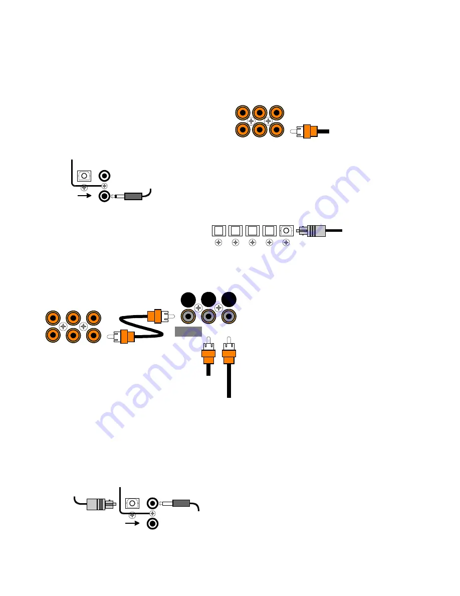
Connect digital inputs (DVD, VLD, etc.) to the A/V System Controller. You will need either coaxial or optical digital
inputs to play Dolby Digital (AC-3) or DTS surround sound processing. Digital connections are also recommended
for PCM sources. If your source has both optical and coaxial outputs connect only one. 

Coaxial digital inputs - standard RCA type
connectors. Attach one end of your digital coaxial
cable to your source coaxial digital out and the other
end to the appropriate A/V System Controller coaxial
digital (orange) input. 

3.5 mm
coaxial digital input - You may connect the V3 coaxial input using a
3.5 mm mono jack instead of the RCA type jack. This input works the
same as the other digital inputs but uses a 3.5 mm mono jack instead
of an RCA. The plug must be wired as tip (+) and the long barrel
section (-).

Optical digital inputs - First, remove the cap on
the optical digital input. Save the cap. Attach one
end of your digital optical cable to your source
and the other end to the appropriate digital input
on the back of the A/V System Controller.

Connecting A Laserdisc Player - Dolby Digital
(AC-3) laserdiscs use a special technique called
AC-3 RF to encode the Dolby Digital bitstream. If the
laserdisc player is capable of playing back Dolby
Digital discs it will have a separate output for this
bitstream in addition to the normal coaxial and/or
optical outputs. Do not connect the AC3-RF output
directly to your A/V System Controller. The AC-3 RF
bitstream must first be converted to a normal
(non-RF) Dolby Digital type signal. It is
recommended that a B&K DT-1 be used to convert
and select between the Laser’s AC-3 RF and
PCM/DTS signals. The output from a DT-1 will
automatically select between the connected
PCM/DTS bitstreams and the converted AC-3 RF
Dolby Digital signal. Other AC-3 RF to Dolby Digital
decoders may not make this switch


automatically.

Connect the laserdisc’s AC3-RF output to the DT-1’s AC-3 RF input. Connect either the laserdisc player’s PCM
coaxial or optical digital output (not both) to the DT-1’s coaxial or optical input. Connect the DT-1’s coaxial output
to the desired coaxial digital input on your A/V System Controller.

Digital Outputs - Connect to a digital recorder (CD-R,
minidisc, DAT, personal computer, etc.) This signal is
the same as the incoming digital signal from the
selected source. If your digital recorder has both
optical and coaxial inputs you need only connect one.
The A/V System Controller converts optical to coaxial
and coaxial to optical. You can connect one digital
recorder to the optical output and another recorder to
the coaxial. The coaxial connector is a 3.5 mm type for
direct connection to a personal computer. You will
need an adapter to connect the 3.5mm type to a
standard RCA type coaxial input

12

p/n 12698 Rev. 9808B

Coax digital input
from DVD output

S A T

D V D / V L D

C D

T V - V 3

V 2

V 1

C O A X   D I G I T A L   I N P U T S

DIGITAL OUTPUTS

OPTICAL

3.5mm

COAX

V3

3.5mm

COAX INPUT

3.5 mm digital input
from PC or portable

V2

DVD

CD

SAT

OPTICAL DIGITAL INPUTS

Optical digital output
from source

V1

Coax digital input

from VLD output

S A T

D V D / V L D

C D

T V - V 3

V 2

V 1

C O A X   D I G I T A L   I N P U T S

M A I N

O U T P U T

A C - 3   R F

I N P U T

C O A X

I N P U T

AC-3 RF input

from VLD output

Receiver

D T - 1

DIGITAL OUTPUTS

OPTICAL

3.5mm

COAX

V3

3.5mm

COAX INPUT

3.5 mm digital output
to digital recorder

Optical digital output
to digital recorder

Summary of Contents for p/n 12698

Page 1: ...B K Components Ltd Reference 10 Reference 20 A V System Controller Owner s Manual p n 12698 Rev 9808B ...

Page 2: ...B K Components Ltd 2100 Old Union Road Buffalo New York 14227 2725 p n 12698 Rev 9808B ...

Page 3: ...n 32 Choosing a source 31 Sleep 31 Power On Off 31 Operation 30 FM Tuner Settings 29 AM Tuner Settings 29 Source Levels 28 Speaker Calibration 24 Speaker Size and Delay 24 Setup Configure 22 Surround Mode Operation 22 Edit Source Name 21 Edit Preset Options 18 Display Options 18 User Preference Setup 17 The Menu System 17 Setup 15 Frequently Asked Questions 14 Control outputs IR Inputs 14 Antenna ...

Page 4: ...ng DTS digital sound and coherent acoustics logos are trademarks of DTS Technology LLC All rights reserved Motorola Powered by Motorola Motorola name and logo are registered trademarks of Motorola Inc The Reference 20 may be used to process Dolby Pro Logic and Dolby Digital The Reference 10 may be used to process Dolby Pro Logic Dolby Digital and DTS Accessories included Owners manual Remote contr...

Page 5: ... provide ventilation reduce acoustic feedback and provide protection against scratching the surface the unit is resting on We advise against removing or altering feet Do not stack anything on top of the A V System Controller amplifier source etc Leave a minimum of 3 clearance from the top of the A V System Controller to the next shelf or component The A V System Controller should be located away f...

Page 6: ...and A V preset names assign names to presets inputs or the turn on message Internal Digitally Synthesized AM FM Stereo tuner stores 20 AM and 20 FM channels Analog inputs outputs seven A V inputs and five A V outputs all with stereo audio composite video and S video plus one set of 5 1 channel surround outputs Digital inputs outputs seven coaxial inputs and one coaxial output plus five optical inp...

Page 7: ... squeeze more information into limited space DTS squeezes 5 1 channels into the space normally required for two uncompressed channels while Dolby Digital squeezes 5 1 channels into about the space required for two channels Your A V System Controller automatically detects the bitstream currently being provided from the source and performs the required decompression and surround processing If no dig...

Page 8: ...t only It must be delivered to your A V System Controller over a coaxial or optical digital cable As of the writing of this manual Dolby Digital is commercially available only on DVD Also see Doby Digital RF below It is also possible to create your own Dolby Digital CDs and DATs if you have the recording equipment You can t directly record Dolby Digital onto minidisc or digital compact cassette si...

Page 9: ...o an amplifier Your A V System Controller includes a high quality preamp Processor A processor typically includes the capability to decode one or more surround formats and convert between digital and analog as required Your A V System Controller is capable of decoding the surround formats described above Zone A zone is usually a room with speakers installed in it Your A V System Controller include...

Page 10: ...he A V System Controller requires the power switch to remain on Use the Sleep button for daily on and off of the A V System Controller It places the unit in standby mode that allows turning back on with the remote control Turn the A V System Controller off with the main power switch when not using it for an extended period of time 4 Volume control For controlling system volume Turning the shuttle ...

Page 11: ...Fixed level outputs to an audio or video recorder 9 Zone video outputs Variable level outputs to your video monitors 10 IR in Accepts input from external IR receptors Connect an IR repeater home run to IR IN for controlling the A V System Controller This method of control is useful when the front IR receptor is blocked for example by a cabinet door or to control the A V System Controller from anot...

Page 12: ...troller s front panel and on screen display see SETUP SOURCE NAMES y Also note the length of the cable for each component s connection and describe how it should be routed or draw your routing scheme below your list You may want to label each cable with a name or number at both ends Use high quality connections to maintain high quality audio and video y Think about the type and length of cable you...

Page 13: ... recorder then omit the video connections LINE INPUTS Right audio input from VCR output Composite video input from VCR output S Video input from VCR output V1 Left audio input from VCR output LINE OUTPUTS Right audio output to VCR input Composite video output to VCR input S Video output to VCR input V1 Left audio output to VCR input Attach one end of the audio interconnect cable to the left audio ...

Page 14: ...K DT 1 be used to convert and select between the Laser s AC 3 RF and PCM DTS signals The output from a DT 1 will automatically select between the connected PCM DTS bitstreams and the converted AC 3 RF Dolby Digital signal Other AC 3 RF to Dolby Digital decoders may not make this switch automatically Connect the laserdisc s AC3 RF output to the DT 1 s AC 3 RF input Connect either the laserdisc play...

Page 15: ... OUTPUT 4 PLUS MINUS OUTPUT 5 PLUS MINUS INPUT 2 INPUT 5 INPUT 3 INPUT 1 INPUT 4 Power Amplifier Subwoofer Output Connect an RCA cable from one of the A V System Controller s two SUB outputs part of the surround outputs You may connect a second subwoofer to the other SUB output if desired If your subwoofer does not contain its own amplifier you will need to purchase an external B K or other power ...

Page 16: ...ontrol 3 Z1 Z2 On 12 VDC when zone 1 zone 2 or both zones are turned on Off 0 VDC when both zones are off Control 4 REMOTE It will repeat a received 38 kHz modulated IR signal The A V System Controller will transmit received IR signals even in sleep mode Note The control outputs can output a maximum of 50 mA Check to see that the source you are connecting to the control out requires 50 mA or less ...

Page 17: ...ired only for Dolby Digital AC 3 laserdiscs Do I need to connect both analog and digital audio from my DVD player or other digital audio source to the A V System Controller In general it is simpler to connect both However if you can meet all of the following criteria you need only connect digital 1 I do not use zone 2 Zone 2 is analog only if you use zone 2 you must connect both left and right ana...

Page 18: ...s may not work correctly using your A V System Controller s Z1 output Refer to your monitor or VCR manual To assist you the A V System Controller s on screen display will tell you what video is currently selected whenever you change sources or hit the SEL remote or ENTER remote or front panel key but it cannot switch your monitor or VCR input for you Note that if the currently selected source is S...

Page 19: ...WN ARROWS to move to the desired menu line Pressing SEL or ENTER will activate the next menu NUMERIC KEYS remote only From the remote control you may also go directly to a menu line by typing the corresponding line number If there is another menu below that line it will be activated immediately no ENTER required LEFT RIGHT ARROWS remote or VOLUME KNOB front panel Some menu selections allow you to ...

Page 20: ...o new line select menu page exit menu system SEL MENU move to new line select menu page previous page SEL MENU activate USER PREFERENCE SETUP ENTER SEL or ENTER 4 move to User Preferences UP or DOWN PAUSE or STOP 3 activate menu system MENU MENU 2 turn on A V System Controller A SLEEP AUD or POWER 1 Action From Front Panel From Remote Display Options This menu allows you to setup various aspects o...

Page 21: ...er will look for S video on the selected source If it finds S video it will send it to your Z1 monitor If it finds no S video but does find composite video it will send composite video to your monitor It is up to you to set your monitor accordingly If it finds no video it will send its internal background screen to your monitor If S video was previously detected on the current source then the back...

Page 22: ... 29 5 23 5 7 move to new line adjust parameter previous page MENU change Overlay Type VOLUME KNOB REW or FF 2 move to Overlay UP or DOWN PAUSE or STOP 1 Action From Front Panel From Remote Set the intensity of the front panel display or turn it off DISPLAY OPTIONS 1 Background Color Red 2 Overlay Opaque Bright 3 Front Display Bright 4 Z1 Video Monitor Composite 5 Z1 Tuner Video last 6 Z2 Tuner Vid...

Page 23: ...REFERENCE SETUP MENU MENU 5 select Z2 Tuner Video VOLUME KNOB REW or FF 4 move to Z2 Tuner Video UP or DOWN PAUSE or STOP 3 select Z1 Tuner Video VOLUME KNOB REW or FF 2 move to Z1 Tuner Video UP or DOWN PAUSE or STOP 1 Action From Front Panel From Remote Edit Preset Options This menu allows you to configure your EDIT PRESET menu see OPERATION PRESETS to allow changing only the preset title as you...

Page 24: ...on This menu allows you to set the level of automation your A V System Controller will apply in choosing a surround mode and make a special setup for stereo listening Check that you are in USER PREFERENCE SETUP and that the remote is in AUDIO mode Set Surround Operation Most users wll prefer the factory setting AUTOMATIC In this mode the A V System Controller automatically sets the surround mode t...

Page 25: ...ATION to LARGE We do not recommend using the LARGE setting if you use small satellite or bookshelf speakers as the bass information even in stereo music may damage the speakers at high volume levels Some users may prefer the sound of their source s or separate digital to analog converter over the converter contained in the A V System Controller but still wish to use the A V System Controller s con...

Page 26: ...y have a center channel speaker and you do not perform this setup procedure the center channel information will be lost If you perform this setup correctly the A V System Controller will know that you have no center channel speaker and send this information to your front left and right speakers along with the normal front left and right information so no audio information is lost About Speaker Siz...

Page 27: ... Subwoofer Front Hi Pass to Front Front Bass to Subwoofer Front Hi Pass to Front Small Subwoofer Off Subwoofer On Subwoofer Ultra Front L R setting Set the size for your center speaker SPEAKER SIZE SETUP 1 Front L R 17 5 60 2 Center 3 Rear L R 4 Subwoofer 5 LFE 6 Center Delay 7 Rear Delay adjust parameter previous page MENU move to new line Small Small Small Yes Normal 0 ms 0 ms choose speaker siz...

Page 28: ...ll to Front Rear Bass to Subwoofer Rear Hi Pass to Front Rear Bass to Sub Rear Hi Pass to Front Off Subwoofer Off Front Small Subwoofer Off Front Large Subwoofer On Subwoofer Ultra Rear setting Setup your subwoofer SPEAKER SIZE SETUP 1 Front L R 68 22 5 6 2 Center 3 Rear L R 4 Subwoofer 5 LFE 6 Center Delay 7 Rear Delay adjust parameter previous page MENU move to new line Small Small Small Yes Nor...

Page 29: ...rom the front distance Use this number for your delay setting 1 foot is roughly equal to 1 ms If the result is negative set the delay to zero If the result is greater than 5 feet set the delay to 5 ms Ideally your front and rear speakers will be the same distance away from your listening area If this is the case leave the Rear Delay set to 0 However physical limitations often require placing the r...

Page 30: ...able to select that speaker in the SPEAKER CALIBRATION menu Also note that the VOL on the remote will not function in this menu SPEAKER CALIBRATION 1 Left HIW GE SETUP MENUS 1 Speaker Size and Delay 2 Speaker Calibration 3 Source Levels 4 AM Tuner Channels 63 5 DOLEUDWLRQ move to new line select menu page previous page SEL MENU 5 FM Tuner Channels 2 Center 3 Right 4 Right Rear 5 Left Rear 6 Subwoo...

Page 31: ...e to adjust SOURCE step to source desired source 3 activate SOURCE LEVEL ENTER SEL or ENTER 2 move to Source Levels UP or DOWN PAUSE or STOP 1 Action From Front Panel From Remote AM Tuner Settings This set up allows you to preset up to 20 AM tuner channels for fast access This is for your convenience only and need not be performed unless you wish to Manual Tuning Quick presses of LEFT RIGHT or tur...

Page 32: ...reo Mono Programming a channel to Stereo will play the channel in stereo if it is broadcast in stereo or in mono otherwise Programming a channel to Mono will force the channel to mono regardless of the broadcast Use mono to reduce background noise on weak channels FM TUNER SETTINGS 0 67 K change frequency previous page MENU FM Stereo 103 3 Channel 15 change channel SETUP MENUS 1 Speaker Size and D...

Page 33: ...its internal memory You may want to turn off the main power switch when your A V System Controller will be idle for extended periods of time or during periods of power line fluctuations Your A V System Controller will not lose its memory while the main power switch is off 3 6 7 BK Powering Up Please Wait main power on off POWER ON OFF can t turn off main power from remote Action From Front Panel F...

Page 34: ...lect TAPE monitor TAPE will appear on Z1 out SOURCE step quickly to TAPE TAPE wait a few seconds while A V System Controller analyzes selected source select desired source or TUNER source will appear on TAPE and V1 outs SOURCE step to source desired source Action From Front Panel From Remote Note The tape monitor loop only allows recording of analog inputs If you simply choose the source you wish ...

Page 35: ...articular movie or a movie has too much bass etc You can temporarily adjust the center rear and subwoofer settings without changing the permanent settings you made in the SPEAKER CALIBRATION setup 17 5 Center Volume 0 dB CENTER LEVEL CENTER LEVEL adjust balance Note only in STEREO mode can t adjust from front panel REW or FF adjust rear delay can t adjust from front panel DELAY or DELAY adjust sub...

Page 36: ...LFE L R M M M M Mono Stereo Pro Logic Dolby Digital 2 0 Dolby Digital 2 0 Stereo Dolby Digital 5 1 DTS 5 1 Surround 3 Stereo Hall 3 Stereo Stereo Hall Stereo F R Stereo Stereo Lt Rt Headphone L R LF C LR LFE RF C RR LFE L M M R M L R L R L M M R M L R L R L R L R L R L R L R L R L M M R M L R L R L M M R M L R L R L R L R L R L R LF C RF LR LFE RR LF C LFE LR RR RF C LFE LR RR M mono same informat...

Page 37: ...nd DTS Your tape outputs contain the same audio information as your left and right front speaker outputs If you make a tape in a normal listening mode such as SURROUND then the center and rear information will not appear on the tape Since the center channel contains much of the dialog for movies the tape will be almost useless STEREO Lt Rt mode allows you to make a tape with little loss of informa...

Page 38: ...y PCM CDs This problem does not apply to DTS DVDs We have provided an override to eliminate this extraneous sound at the cost of automatic bitstream detection If you find the extraneous sound unacceptable engage the DTS override before playing your DTS disc Remember that if you subsequently try to play any non DTS material you will need to manually switch back to auto plug and play operation Dolby...

Page 39: ...make all settings you wish to save make all settings you wish to save 1 Action From Front Panel From Remote Recalling Saving Presets via the Menu System You can also recall and save presets via your A V System Controller s menu system from the remote or from the front panel If using the remote be sure it is in AUDIO mode if not press AUDIO exit menu system MENU MENU 10 return to main menu MENU MEN...

Page 40: ... or ENTER Action From Front Panel From Remote ZONE 2 OPERATION Via the Front Panel You can control zone 2 from your A V System Controller s front panel by using the LEVEL button to step to ZONE 2 The front panel will now control zone 2 After a few seconds of inactivity control will return to zone1 The SLEEP PRESET ENTER UP DOWN ARROWS SOURCE and VOLUME KNOBS will function exactly as for zone 1 MEN...

Page 41: ...efer to SETUP Advanced Systems Settings will appear as line 6 in SETUP MENUS Make sure your A V System Controller is on and the remote is in AUDIO mode Advanced Security Options 1 Advanced Menu Visible 2 Memory Lock No 9 1 9 6 move to new line previous page MENU adjust parameter set to Hidden recommended or Visible VOLUME KNOB REW or FF 3 move to Advanced Menu UP or DOWN PAUSE or STOP 2 enable adv...

Page 42: ...front panel or remote operation WARNING If you set this level too low the A V System Controller may appear broken no sound ADVANCED ZONE SETTINGS 2 Z1 Product ID 1 3 Z1 On Screen Enabled 0 9 move to new line previous page MENU 4 Z2 Level Control Variable 5 Z2 Max Level 15 dB ADVANCED SYSTEM SETUP 1 Zone Configuration 2 Power On Titles 21 6 783 move to new line previous page MENU select menu page S...

Page 43: ...led move to new line previous page MENU 4 Z2 Level Control Variable 5 Z2 Max Level 15 dB 1 Z1 Max Level 15 dB 6 Z2 Product ID 2 adjust parameter ADVANCED ZONE SETTINGS 2 Z1 Product ID 1 3 Z1 On Screen Enabled move to new line previous page MENU 4 Z2 Level Control Variable 5 Z2 Max Level 15 dB 1 Z1 Max Level 15 dB 6 Z2 Product ID 2 adjust parameter set desired product ID VOLUME KNOB REW or FF 4 mov...

Page 44: ...E or STOP 1 Action From Front Panel From Remote Z2 Max Fixed Level Z2 max level allows you to set a maximum volume level for zone 2 This is very useful if you are using speakers that can t handle the maximum power output from your external amplifier or if you simply wish to limit the volume that can be achieved using normal front panel or remote operation If you have chosen zone 2 fixed level abov...

Page 45: ...s move to new line previous page MENU select menu page SEL 4 Security Options 3 Control Out return to ADVANCED SYSTEM SETUP MENU MENU 11 edit Line 2 repeat 4 8 repeat 4 8 10 move to Power On Line 2 UP or DOWN PAUSE or STOP 9 finish editing line 1 ENTER SEL or ENTER 8 continue changing characters repeat 5 6 repeat 5 6 7 move to new character VOLUME KNOB REW or FF 6 change blinking character UP or D...

Page 46: ...l amplifiers HEADPHONE is a global setting for all sources if you set HEADPHONE for one source it will be set for all other sources CONTROL OUT SETUP for DVD 9 3 21 6 move to new line previous page MENU 2 Control Out 2 Zone 2 21752 287 adjust parameter AUD to select control 1 Control Out 1 Phones 3 Control Out 3 Z1 Z2 4 Control Out 4 Remote Using AV system controller select a source to setup ADVAN...

Page 47: ...ut 4 Remote Using AV system controller select a source to setup return to normal operation MENU MENU 10 return to MAIN MENU MENU MENU 9 return to SETUP MENUS MENU MENU 8 return to ADVANCED SYSTEM SETUP MENU MENU 7 set control out 3 and 4 repeat 1 5 repeat 1 5 6 set control out 2 for other sources repeat 2 4 repeat 2 4 5 set desired control out VOLUME KNOB REW or FF 4 return control to A V System C...

Page 48: ...mode 4 Check speaker setup 5 Speakers phase wrong Surround sound does not sound correct 1 Check all connectors and repair as necessary 2 Check ground of outlet Have it checked by qualified serviceman 3 Check ground 4 Reposition cables 1 Poor ground connection in interconnect cables 2 Poor ground in main AC supply 3 Poor ground on cable box 4 Cables running across back of TV Loud hum or buzz on one...

Page 49: ...y 2 dB Capture Ratio 28 dBf Sensitivity 20 Hz 15 kHz 1 3 dB Frequency Response Less than 0 3 Total Harmonic Distortion Less than 0 25 Total Harmonic Distortion 520 1620 kHz Frequency Range 87 5 107 9 MHz Frequency Range AM section Tuner Specifications FM Section Tuner Specifications 1 1 Digital Outputs coax optical 7 5 Digital Inputs coax optical 5 Video Outputs 5 Audio Analog Outputs 7 Video Inpu...

Page 50: ...LES EDIT SOURCE NAME change position previous page M E N U DEFAULT USER DVD DVD change character AUD to select control select source to rename Using AV system controller SURROUND MODE OPERATION 1 Surround Operatio Auto Dolby Digital DTS 5 1 overrides MODE setting 2 Stereo Operation Normal STEREO MODE is digital Front L R speaker size move to new line adjust parameter exit menu system M E N U from ...

Page 51: ...REAR PANEL ENLARGED VIEW 49 p n 12698 Rev 9808B ...

Page 52: ...B K Components Ltd 2100 Old Union Road Buffalo New York 14227 716 656 0023 www bkcomp com 50 p n 12698 Rev 9808B ...

Reviews: