| 11
Wiring |
Zeus2 Installation Manual
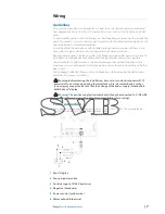
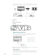
NMEA 2000 – connection to backbone
Device connection
The Zeus2 multi function displays are equiped with an NMEA 2000 data port, which allows the
receiving and sharing of a multitude of data from various sources.
Essential network information
•
The standardised physical cables/connectors for NMEA 2000 are ‘Micro-C’ and ‘Mini-C’,
directly derived from the automation industy’s ‘DeviceNET’ - ‘Micro-C’ being the more
commonly used size.
•
A network consists of a linear ‘backbone’ from which ‘drop cables’ connect to NMEA 2000
compliant devices
•
A single drop cable has a maximum length of 6 m (20 ft). The total length of all drop cables
combined should not exceed 78m (256 ft)
•
A NMEA 2000 network, using Micro-C cabling, has a maximum cable length of 100 m (328 ft),
between any two points
•
A NMEA 2000 network needs to have a terminator at each end of the backbone. A terminator
can be one of the following:
•
a terminator blank plug
•
a wind transducer (where the mast cable is one end of the backbone)
Planning and installing a network backbone
The Micro-C backbone needs to run between the locations of all products to be installed -
typically in a bow to stern layout - and be no further than 6 m from a device to be connected.
Choose from the following components to make up the backbone:
•
Micro-C cables: 0.6 m (2 ft), 1.8 m (6 ft), 4.55 m (15 ft), and 7.58 m (25 ft) cables
•
T-connector. Used to connect a drop cable to the backbone
•
Micro-C power cables. Connected to backbone via a T-connector
Note:
When using a wind sensor, the mast cable should be connected at one end of the
backbone, as the sensor is fi tted with a termination resistor.
Note:
Most NMEA 2000 devices can be connected directly to a SimNet backbone and SimNet
devices can be connected to a NMEA 2000 network by using adapter cables.
Note:
B&G devices are fully compatible with a SimNet network by using a Micro-C to SimNet
adapter cable.
Note:
Triton displays have two Micro-C connectors, and can either be connected inline with
the backbone, or wired individually off a drop cable. Connecting from device to device is
known as ‘daisy chaining’ This network topology is not offi
cially NMEA 2000 compliant.
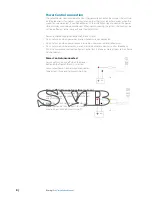
Power the network
The network requires its own 12 V DC power supply protected by a 5 amp fuse or breaker. For
vessels fi tted with 24 V systems, use a DC-DC converter to supply 12 V.
Connect power at any location in the backbone for smaller systems.
For larger systems introduce power at central point in the backbone to “balance” the voltage
drop of the network.
Note:
If joining to an existing NMEA 2000 network that already has its own power supply, do
not make another power connection elsewhere in the network, and ensure existing network
is not powered by 24 V DC.
Note:
Do not connect the NMEA 2000 power cable to the same terminals as the engine start
batteries, autopilot computer, radar, bow thruster or other high current devices.
Summary of Contents for Zeus2 series
Page 1: ...ENGLISH Zeus2series Installation Manual bandg com ...
Page 2: ......
Page 6: ......
Page 47: ......
Page 48: ......
Page 49: ......
Page 50: ...0980 988 10604 001 ...


