background image

NETWORK COMPASS USER MANUAL 


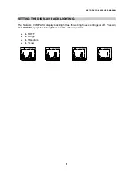
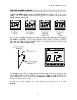
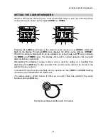
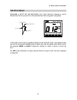
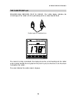
THE HEAD/LIFT DISPLAY 

 
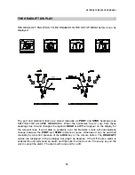
THE HEAD/LIFT PAGE HAS TO BE ENABLED IN THE SETUP MENU before it can be 
displayed. 


MODE

TIMER

LOCK

SETUP

LIGHTS

ENTER

Network COMPASS

HEAD

30

20

10

30

20

10

PORT

MODE

TIMER

LOCK

SETUP

LIGHTS

ENTER

Network COMPASS

HEAD

30

20

10

30

20

10

STBD

MODE

TIMER

LOCK

SETUP

LIGHTS

ENTER

Network COMPASS

LIFT

30

20

10

30

20

10

STBD

MODE

TIMER

LOCK

SETUP

LIGHTS

ENTER

Network COMPASS

LIFT

30

20

10

30

20

10

PORT


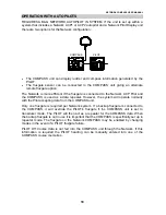
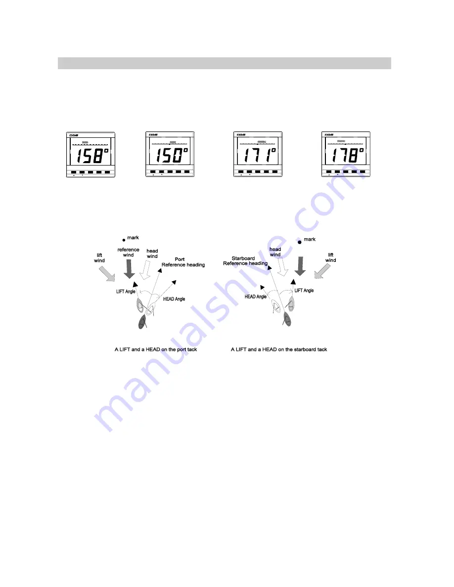
The port and starboard tacks are stored manually as 

PORT

 and 

STBD

 headings (see 

SETTING THE COURSE MEMORIES). When the helmsman has to vary from these 
headings due to wind changes the legends 

HEAD

 or 

LIFT

 will appear on the display for 

the relevant tack. If wind data is available over the Network a tack will automatically 
change between the 

PORT

 and 

STBD

 reference course. Otherwise it can be switched 

manually by two short presses of the 

LOCK

 key or the remote button. The 

HEAD/LIFT


values are displayed in the analogue bar graph as degrees. If the Off Course alarm is 
enabled the unit will sound an alarm and flash 

-A-

 if a head occurs. Press any key on the 

unit to cancel the alarm. The alarm will not sound for a lift. 


11

Summary of Contents for Network COMPASS unit

Page 1: ...DDER DISPLAY 10 THE HEAD LIFT DISPLAY 11 USING THE TIMER 12 SETTING THE TIMER 13 ENABLING DISABLING THE TIMER BEEPS 13 ENABLING THE OFF COURSE ALARM 14 SETTING THE COMPASS DAMPING 14 SETTING THE COMPA...

Page 2: ...any combination of units can be linked into a Network with units processing their own data or acting as repeaters for data from other units This Network provides a comprehensive navigational system Sc...

Page 3: ...ument System The unit can also operate as a repeater of course data received via the Network These connections plug directly into the rear of the display The Network COMPASS includes two adjustable al...

Page 4: ...these should be linked to a fluxgate and set to transducer mode the others must be set to repeater mode Refer to SELECTING THE DISPLAY MODE to see how to change modes In this configuration the main un...

Page 5: ...teristics of the fluxgate sensor so if it is to be used with a fluxgate that is in transducer mode the fluxgate should be installed and connected before applying power Refer to the installation guidel...

Page 6: ...ttings or off Pressing the LIGHTS key cycles through these in the following order L 0 OFF L 3 High L 2 Medium L 1 Low MODE TIMER LOCK SETUP LIGHTS ENTER Network COMPASS MODE TIMER LOCK SETUP LIGHTS EN...

Page 7: ...y with Network Pilot The Off Course display The Head Lift display if enabled The unit will autodetect the presence of a GPS or PILOT on the Network and will activate the displays accordingly The Off C...

Page 8: ...five seconds after the last key is pressed Alternatively the displayed course memory can be reset by sailing on a heading then depressing the LOCK key for two seconds The current course will then be...

Page 9: ...ENTER Network COMPASS 10 1 0 0 1 XTE 10 1 0 0 1 PORT STEER In this instance the vessel is heading starboard of the planned course The display shows the current bearing and the XTE scale is visible ab...

Page 10: ...ly useful on wheel steered boats MODE TIMER LOCK SETUP LIGHTS ENTER Network COMPASS 30 20 10 30 20 10 RUDDER The vessel is turning to starboard the display shows the current heading and the rudder sca...

Page 11: ...tored manually as PORT and STBD headings see SETTING THE COURSE MEMORIES When the helmsman has to vary from these headings due to wind changes the legends HEAD or LIFT will appear on the display for t...

Page 12: ...e left to time zero There are no beeps after time zero The beep sequences are shown in the table below Beeps begin at Beeps end at Number of beeps Frequency 60 hours 1 hour 5 every hour 1 hour 10 minu...

Page 13: ...inutes before time zero up to 30 minutes 6 Alter the minutes using the or keys 7 Press ENTER to set the timer with the seconds set to zero Both sides of the bar graph will now be full to show that the...

Page 14: ...return to setup mode 5 Press MODE to return to desired mode MODE TIMER LOCK SETUP LIGHTS ENTER Network COMPASS OFFCOURSE SETTING THE COMPASS DAMPING Compass damping is used to smooth out compass read...

Page 15: ...p mode 5 Press MODE to return to the desired mode MODE TIMER LOCK SETUP LIGHTS ENTER Network COMPASS MODE TIMER LOCK SETUP LIGHTS ENTER Network COMPASS Compass Offset at 3 Compass Offset at 7 SETTING...

Page 16: ...R Network COMPASS TRUE MODE TIMER LOCK SETUP LIGHTS ENTER Network COMPASS TRUE Compass will display TRUE headings Compass will display MAGNETIC headings ENABLING THE HEAD LIFT MODE 1 Press SETUP until...

Page 17: ...wing This starts with a re phasing of the fluxgate signals which takes about 20 seconds see INITIAL POWER UP The display shows PHS and a pair of chevrons which move as successive phases are tested Whe...

Page 18: ...d to the Network ACP Pilot and the COMPASS is used as a data repeater However the system will operate normally with the Pilot accepting data from the COMPASS unit Only one fluxgate is required per Net...

Page 19: ...onboard metallic object Calibration manoeuvre attempted near to large metallic vessel or equipment e g loading crane Display shows a number and the Error message Switch off and restart If alarm buzze...

Page 20: ...for the self tapping screws the fixing stud holes and the mounting bracket The template allows 4mm 5 32 between adjacent units for the suncover increase this distance if required to maximum of 60mm 2...

Page 21: ...ly mounted on steel hulled vessels Well protected from physical damage With the connector downwards MOUNTING THE FLUXGATE Secure the unit in the selected site using the self tapping screws provided Ro...

Page 22: ...e gasket around the mounting bracket Rubber Gasket Gasket Display Unit Sun cover Self tapping screws Mounting bracket 70 0mm hole 25 0mm 65 0mm 110 0mm 110 0mm Network COMPASS LIGHTS ENTER SETUP TIMER...

Page 23: ...ICAL Power Supply 12V DC nominal 10V to 16V Operating Current 40 mA to 100 mA Protection Connect via external fuse or circuit breaker CABLES AND CONNECTIONS Connection to adjacent units and other equi...

Reviews:

Related manuals for Network COMPASS unit