


Troubleshooting
52
Manual Documentation Number: ZXTx-IO-x-0712m
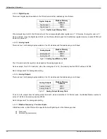
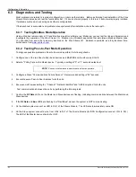
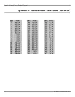
7.1.1 Testing DI
On System-1 connect one side of the switch to the DI on the Zlinx Xtreme I/O device and the other side of the switch to high or
ground depending on PNP or NPN configuration (see Figure 7-2). The LED corresponding to the DI should be ON
PWR IN +
DIx
(a) PNP (Sourcing) Input Wiring
with Internal Power Supply
DIx
(b) NPN (Sinking) Input Wiring
with Internal Power Supply
Com
Figure 7-2
Digital Input (Sourcing driver) wiring
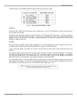
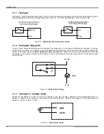
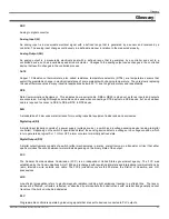
7.1.2 Testing DO (Relay O/P)
To test a “relay” output the following can be performed. See “Appendix E: Zlinx Xtreme I/O Models and Features” to find out
which modules are relay. On System-1 on the corresponding Zlinx Xtreme I/O device connect a Light through COM and NO
contact of the relay output (see
Error! Reference source not found.
3). Make sure to check the polarity of the LED while
connecting it. On System-2 perform contact closure on the corresponding DI. The relay output should turn ON and the Light
should turn ON
NO
Com
NC
V+ / Ph
V- / N
Light
Figure 7-3
Relay Output Testing
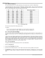
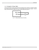
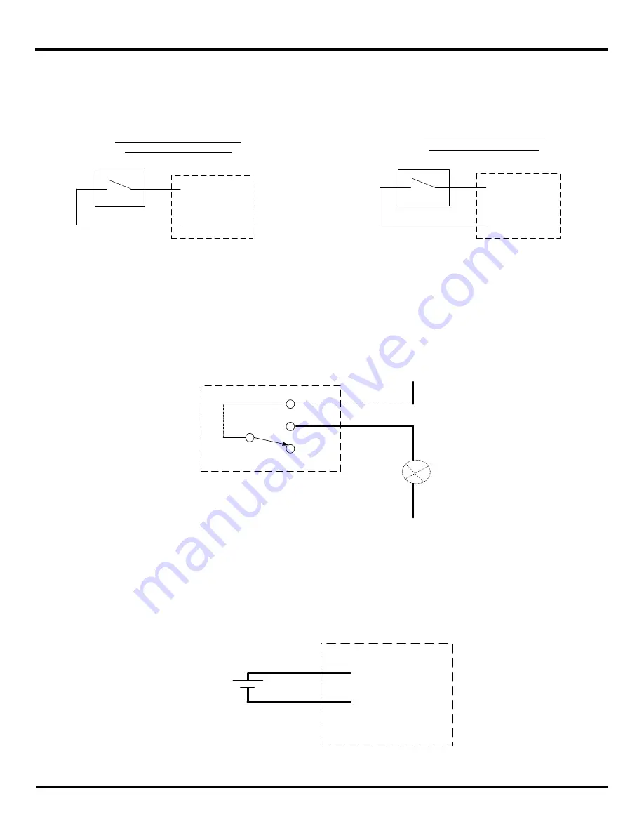
7.1.3
Testing AI in “Voltage” Mode
Connect an AA battery (1.5 VDC) on the AI-1 on System-1 (see Fig 7-4) and a voltmeter on the corresponding AO-1 on
System-2. Make sure the polarity is correct while connecting the battery. Measure the voltage on the Analog Output on
System-2. It has to indicate 1.5 VDC.
AINx
COM
+
-
Figure 7-4
Analog Input wiring
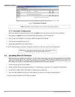
Summary of Contents for ZXT24-IO-222R2
Page 6: ......


