


E
N
G
L
I
S
H
6 / 18
0006080304_201107
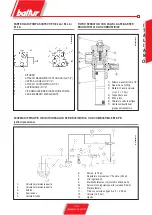
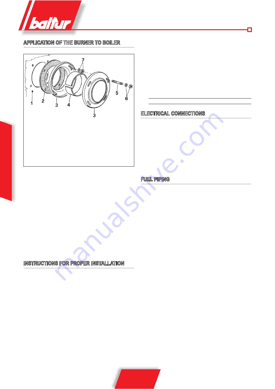
APPLICATION OF THE BURNER TO BOILER
1 - Boiler plate
2 - Insulating gasket
3 - Burner fixing flange
4 - Elastic collar
5 - Stud bolt
6 - Locking nut with washer
7 - Nut and washer for fastening the first flange
N°
0002933330
N.B.
To tighten flanges, hold the burner body up so that the combu-
stion head is in the horizontal position. The flange must be
applied to the burner's combustion head, in the right position
to ensure that it penetrates the furnace properly (the depth
of penetration of the head must be specified by the boiler
manufacturer).
The burner is applied correctly if the preheater tank is slightly inclined
(higher on the side on which fuel flows out toward the nozzle). This
prevents gas from accumulating in the tank. The presence of gas
in the preheater considerably increases the amount of time required
to pressurize fuel, so that the burner is likely to shut down. During
application to the boiler, make sure that the burner is not installed in
such a way that there is no inclination or, even worse, the preheater
is inclined in the opposite direction.
INSTRUCTIONS FOR PROPER INSTALLATION
Before proceeding with installation make sure that:
1) The flue (cross-section and height) corresponds to the regula-
tions in force.
2) When refractory lining of the combustion chamber is necessary
(where the boiler type so requires) you must follow the boiler
manufacturer’s instructions to the letter.
3) The burner electricity supply must be connected up as illustra-
ted in our diagram and on-burner electrical connections must
be compatible with power supply voltage.
4) Fuel lines must be set up as illustrated in our diagrams.
5) The burner nozzle (or nozzles) must be compatible with the
boiler output. Replace with others if necessary. Under no
circumstances must the fuel flow-rate be greater than the ma-
ximum required by the boiler or maximum admissible burner
flow-rates. Bear in mind that the combustion head has been
designed for nozzles with a 45° spray angle. Only in exceptional
cases may nozzles of a different angle be fitted: in such cases
make sure that these differently-angled nozzles do not cause
any problems (flame detachment, staining of diffuser disc or
combustion head, violent ignition, etc.).
6) Exercise caution during removal of the protective plastic nozzle
plug: if the seal is compromised (a slight scratch will damage
it) the fuel could drip.
7) Make sure that the burner draught tube penetrates the combu-
stion chamber as per the boiler manufacturer’s specifications.
ELECTRICAL CONNECTIONS
All connections must be carried out with flexible wiring.
Ensure there is always a safe gap between electrical wiring and
any hot parts.
Make sure that the power line to which the unit will be connected
has voltage/frequency ratings suitable for the burner.
Make sure that the main line, the relative switch and fuses (indi-
spensable) and any limiting device are able to withstand the maxi-
mum current absorbed by the burner. For details see the burner-
specific wiring diagrams.
FUEL PIPING
The explanation that follows exclusively bears in mind that which is
necessary to ensure proper operation.
The unit is equipped with a self-priming pump able to draw the oil
directly from the tank even on first filling.
This is true as long as there are the necessary conditions (see the
table regarding horizontal and vertical distances and the viscosity-
temperature diagram). To ensure proper operation the piping
(suction and return) is made with welded couplings to eliminate the
need for threaded joints which often bleed in air and consequently
compromise performance of the pump and therefore the burner
too. Where detachable couplings are indispensable use the welded
flange system with an in-between fuel-resistant gasket to provide
an excellent seal. For those systems needing pipes of a relatively
small diameter we recommend the use of copper pipes. In those
unavoidable couplings we recommend the use of “biconical” fit-
tings. The enclosed tables show the general diagrams for various
unit types according to relative positioning of the tank and burner.
Suction piping must run “uphill” towards the burner to prevent any
bubbles lodging in the pipe. Should more than one burner be in-
stalled in a single boiler room each burner must be equipped with
its own suction pipe. Only return pipes may link up in a single pipe
designed to reach the tank. Always avoid connecting the return pipe
directly to the suction pipe.
It is always good practice to insulate the suction and return piping
tp prevent damaging over-cooling. Pipe diameters (which must be
strictly adhered to) are given in the following tables. The maximum
vacuum the pump is able to support while continuing to operate
effectively and silently is 35 cm Hg. Should this limit be exceeded
proper pump performance cannot be guaranteed. Maximum suction
and return pressure = 1 bar.
When a fuel oil with a viscosity in excess of the pumping limit (see
diagram) is used it must be heated to a temperature that allows it
Summary of Contents for BT 17 SPN
Page 2: ......
Page 4: ......
Page 44: ...2 20 0006080304_201107 BALTUR a b c a b c d e f g...
Page 45: ...3 20 0006080304_201107 2 RC a b c d e a b a b c d...
Page 48: ...6 20 0006080304_201107 N 0002933330 1 2 3 4 5 6 7 1 2 3 4 5 45 6 7...
Page 49: ...7 20 0006080304_201107 35 1 5 5 50 30...
Page 54: ...20 0006080304_201107 25 1 12 5 20 1 2 1 1 27 27 27 25 p 2 18 1 1...
Page 56: ...20 0006080304_201107 1 2 L1 L2 L3 3 4 5 1 2 2800 6 7 8 BT 8608 1 BT 8605 1 a 45 1 2 2 1...
Page 57: ...20 0006080304_201107 3 4 5 2 1 6 1 2 7 2 8 2 9 2 7 CO2 10 13 6 Bacharach 10 15 2 1 2 5 a b...
Page 58: ...20 0006080304_201107 c 3 50 5 10 8608 1...
Page 59: ...20 0006080304_201107 0002930500 BT 8608 1...
Page 63: ...63 66 0006080304_201107 16A 16 14...
Page 65: ...65 66 0006080304_201107...


