background image

16

english

6


SSI interface (continued)

6.4 

Synchronous and asynchronous operation

Synchronous operation

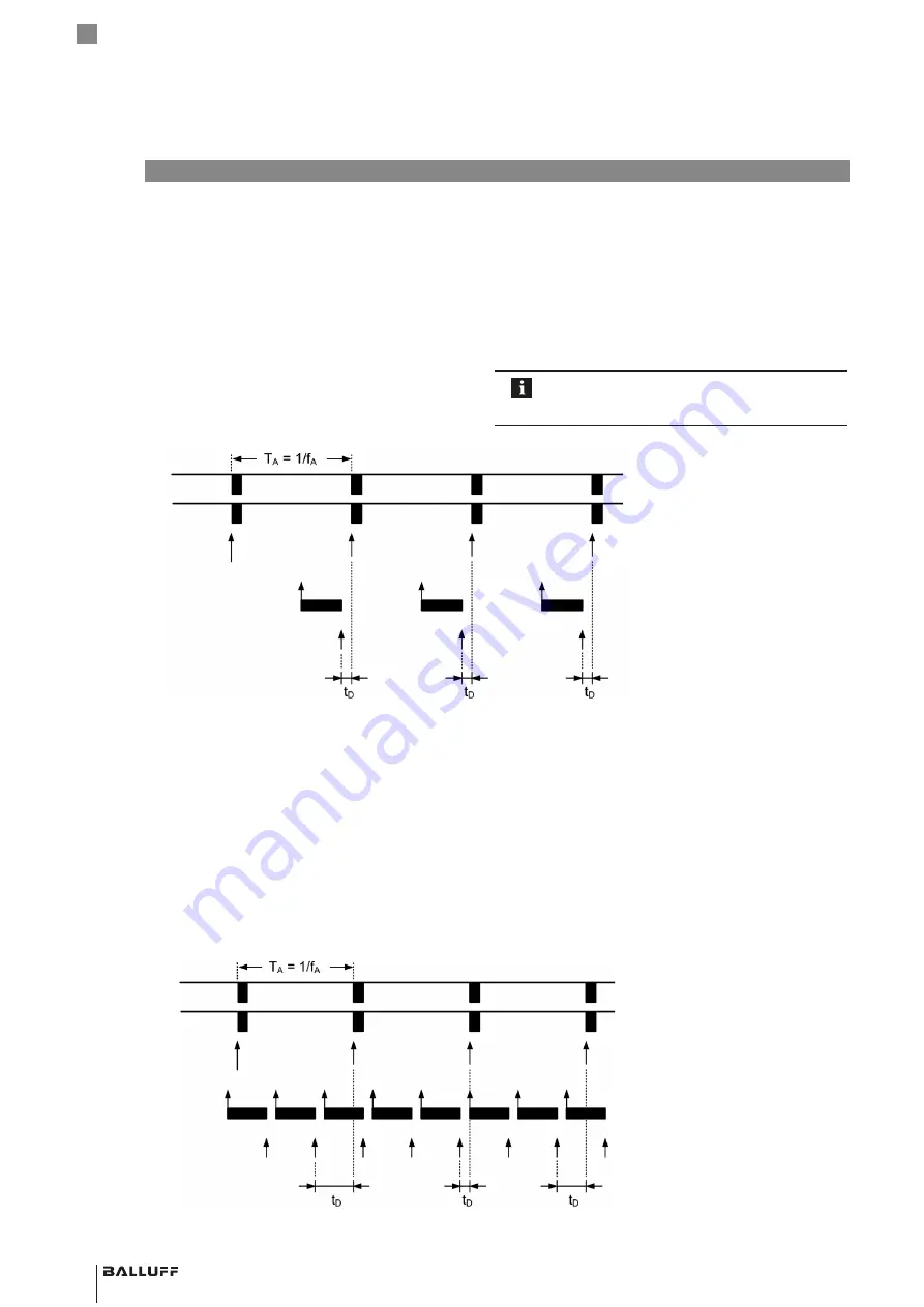
A uniform and brief timing is often required for control 

applications. The position delay t

must be kept as short 

and constant as possible. Synchronous operation is thus 

intended for closed control loops. Here, the internal 

sensing cycle adjusts itself to the external sampling cycle.

The following graphic clarifies this relationship:

Two boundary conditions must be taken into account 

during synchronous operation:
–  The external sampling frequency f

A

 must be in the 

range 62.5 Hz < f

A

 < f

A,max

. The maximum permissible 

sampling frequency f

A,max

 is shown in Fig. 8-1 on 

page 20.

–  The sampling frequency must be kept as constant as 

possible.

The sampling frequency is the reciprocal value of 

the time between two clock packages and may 

not be confused with the SSI clock frequency.

Asynchronous operation

During asynchronous operation, the external sampling 

frequency is independent of the internal sampling 

frequency of the transducer. Depending on the external 

query point, the position is more or less current and the 

position delay t

D

 is not constant. In the worst case, it is 

equal to the internal sampling period. The transducer 

always works with the maximum possible internal sampling 

frequency. Due to the measuring principle, the maximum 

sampling frequency f

A,max

 is dependent on the nominal 

length of the transducer.

The following graphic shows the behavior of internal and 

external sampling in asynchronous operation:

Clk

Data

External  

sampling point

New value available

Internal sampling 

point + processing

Position delay

Clk

Data

External 

sampling point

New value available

Internal sampling 

point + processing

Position delay

BTL7-S5_  _(B) -M _ _ _ _ -P-S32/S115/S147/KA_  _/FA_  _

Transducer – Profile Style

Summary of Contents for BTL7-S5-M Series

Page 1: ...Betriebsanleitung BTL7 S5_ _ B M_ _ _ _ P S32 S115 S147 KA_ _ FA_ _ deutsch...

Page 2: ...www balluff com...

Page 3: ...eber 10 4 4 Elektrischer Anschluss 11 4 4 1 Steckverbinder S32 11 4 4 2 Steckverbinder S115 11 4 4 3 Steckverbinder S147 11 4 4 4 Kabelanschluss 12 4 5 Schirmung und Kabelverlegung 12 5 Inbetriebnahme...

Page 4: ...21 9 3 Freie Positionsgeber 22 9 4 Steckverbinder und Kabel 23 9 4 1 BKS S32 S33M 00 frei konfektionierbar 23 9 4 2 BKS S232 S233 PU _ _ konfektioniert 23 9 4 3 BKS S115 S116 PU _ _ konfektioniert 24...

Page 5: ...assungen und Kennzeichnungen UL Zulassung1 File No E227256 1 Nicht bei BTL7 FA_ _ US Patent 5 923 164 Das US Patent wurde in Verbindung mit diesem Produkt erteilt Mit dem CE Zeichen best tigen wir das...

Page 6: ...e Sicherheitsma nahmen treffen kann Der Betreiber hat die Verantwortung dass die rtlich geltenden Sicherheitsvorschriften eingehalten werden Insbesondere muss der Betreiber Ma nahmen treffen dass bei...

Page 7: ...llen siehe Zubeh r ab Seite 21 Nennl nge Um den Wegaufnehmer optimal an die Anwendung anzupassen sind Nennl ngen von 50 mm bis 7620 mm lieferbar Bild 3 1 Wegaufnehmer BTL7 Aufbau 3 Aufbau und Funktion...

Page 8: ...indigkeit mit und ohne Vorzeichen Geschwindigkeitsdifferenz 3 3 LED Anzeige Bild 3 2 LED 2 LED 1 LED Anzeigen BTL7 LED 1 Gr n Normalfunktion Positionsgeber ist innerhalb der Grenzen Rot Fehler Kein Po...

Page 9: ...siehe Bild 3 1 1 Wegaufnehmer in die Befestigungsklammern f hren 2 Wegaufnehmer mit den Befestigungsschrauben auf dem Untergrund fixieren Schrauben in den Klammern mit max 2 Nm festziehen 3 Postionsg...

Page 10: ...800 2 0 1 4 mm 2 mm BTL5 P 5500 2 5 15 mm 15 mm BTL5 P 4500 1 0 1 2 mm 2 mm BTL6 A 3800 2 4 8 mm2 5 mm BTL6 A 3801 2 4 8 mm2 5 mm 1 Der gew hlte Abstand muss ber die gesamte Messl nge konstant bleiben...

Page 11: ...ufneh mer 8 poliger Rundstecker M16 4 Einbau und Anschluss Fortsetzung 4 4 2 Steckverbinder S115 BTL7 Standard BTL7 USB Configurable Pin BTL7 S5_ _ S115 BTL7 S5_ _B S115 BTL7 S510 S115 BTL7 S510B S115...

Page 12: ...kerausf hrung Schirm im Steckverbinder mit dem Steckergeh use fl chig verbinden Kabelausf hrung Wegaufnehmerseitig ist der Kabel schirm mit dem Geh use verbunden Magnetfelder Das Wegmesssystem ist ein...

Page 13: ...lagen oder Systemher stellers beachten 1 Anschl sse auf festen Sitz und richtige Polung pr fen Besch digte Anschl sse tauschen 2 System einschalten 3 Messwerte und einstellbare Parameter pr fen und gg...

Page 14: ...ng bleibt so lange auf Low bis die tm Zeit abgelaufen ist Danach ist der Wegaufnehmer f r das n chste Clock paket wieder empfangsbereit Clk Data TClk tv tv Clk Data MSB LSB TClk 1 2 3 4 5 n n 1 tm SSI...

Page 15: ...ich der Positionsgeber von der Anschlussseite bei negati ven Geschwindigkeiten bewegt er sich auf die Anschluss seite zu Die Steuerung muss dann auf die Verarbeitung von signed Daten eingestellt sein...

Page 16: ...n und darf nicht mit der SSI Clockfrequenz verwechselt werden Asynchroner Betrieb Beim asynchronen Betrieb ist die externe Abtastfrequenz unabh ngig von der internen Abtastfrequenz des Wegauf nehmers...

Page 17: ...sen Positionsgeber auf Wegaufnehmer Funktionen des Ausgangs Position Position im Messbereich Geschwindigkeit Geschwindigkeit des Positionsge bers das Vorzeichen zeigt die Bewegungsrichtung an Eine Bew...

Page 18: ...P67 Kabel IP684 3 8 3 Spannungsversorgung Spannung stabilisiert6 10 30 V DC Restwelligkeit 0 5 Vss Stromaufnahme bei 24 V DC 100 mA Einschaltspitzenstrom 500 mA 10 ms Verpolungsschutz bis 36 V Versorg...

Page 19: ...g Kabeltemperatur 40 C 90 C Kabeldurchmesser max 7 mm zul ssiger Biegeradius feste Verlegung 35 mm bewegt 105 mm BTL7 FA_ _ Kabelmaterial PTFE keine UL Zulassung verf gbar Kabeltemperatur 55 C 200 C K...

Page 20: ...stfrequenz bei Geschwindigkeitsausgabe ist auf 3 3 kHz begrenzt Die maximale SSI Taktfrequenz fCLK max ist abh ngig von der Leitungsl nge1 Bild 8 2 Maximale SSI Taktfrequenz in Abh ngigkeit von der Le...

Page 21: ...F 2814 1S Gewicht ca 28 g Geh use Aluminium Gleitfl che Kunststoff BTL5 T 2814 1S 16 5 11 5 28 22 40 M5x10 Bild 9 3 Einbauma e Positionsgeber BTL5 T 2814 1S Gewicht ca 28 g Geh use Aluminium Gleitfl...

Page 22: ...use Kunststoff BTL6 A 3801 2 28 16 21 37 6 4 2 18 13 Bild 9 8 Einbauma e Positionsgeber BTL6 A 3801 2 Gewicht ca 25 g Geh use Kunststoff BTL5 P 4500 1 16 5 45 25 28 15 4 2 25 7 5 M5x8 40 Bild 9 9 Ein...

Page 23: ...fektioniert BKS S232 PU _ _ Steckverbinder gerade umspritzt konfektioniert M16 8 polig Unterschiedliche Kabell ngen bestellbar z B BKS S232 PU 05 Kabell nge 5 m Bild 9 12 20 66 Steckverbinder BKS S232...

Page 24: ...8M 00 frei konfektionierbar BKS S147M 00 Steckverbinder gerade frei konfektionierbar M16 nach IEC 130 9 7 polig Bild 9 17 62 Steckverbinder BKS S147M 00 BKS S148M 00 Steckverbinder gewinkelt frei konf...

Page 25: ...fallend 9 Gray fallend D Gray fallend Aufl sung 1 1 m 3 10 m 5 40 m 7 2 m 9 0 5 m 2 5 m 4 20 m 6 100 m 8 50 m Synchroner asynchroner Betrieb B synchroner Betrieb ohne B asynchroner Betrieb Nennl nge...

Page 26: ...ung 0 1 m Werkseinstellung Synchroner asynchroner Betrieb B synchroner Betrieb ohne B asynchroner Betrieb Nennl nge 4 stellig M0500 metrische Angabe in mm Nennl nge 500 mm M0050 M7620 Bauform P Profil...

Page 27: ...3071 10 0 393700787 Tab 11 1 Umrechnungstabelle mm inch 1 inch 25 4 mm inch mm 1 25 4 2 50 8 3 76 2 4 101 6 5 127 6 152 4 7 177 8 8 203 2 9 228 6 10 254 Tab 11 2 Umrechnungstabelle inch mm 11 Anhang 1...

Page 28: ...173 370 Fax 49 7158 173 691 service balluff de US Service Center USA Balluff Inc 8125 Holton Drive Florence KY 41042 Phone 859 727 2200 Toll free 1 800 543 8390 Fax 859 727 4823 technicalsupport ball...

Page 29: ...User s Guide BTL7 S5_ _ B M_ _ _ _ P S32 S115 S147 KA_ _ FA_ _ english...

Page 30: ...www balluff com...

Page 31: ...ting magnets 10 4 4 Electrical connection 11 4 4 1 Connector S32 11 4 4 2 Connector S115 11 4 4 3 Connector S147 11 4 4 4 Cable connection 12 4 5 Shielding and cable routing 12 5 Startup 13 5 1 Starti...

Page 32: ...21 9 3 Floating magnets 22 9 4 Connectors and cables 23 9 4 1 BKS S32 S33M 00 freely configurable 23 9 4 2 BKS S232 S233 PU _ _ preassembled 23 9 4 3 BKS S115 S116 PU _ _ preassembled 24 9 4 4 BKS S1...

Page 33: ...rovals and markings UL approval1 File no E227256 1 Not for BTL7 FA_ _ US Patent 5 923 164 The US patent was awarded in connection with this product The CE Mark verifies that our products meet the requ...

Page 34: ...t regulations pertaining to the work to be done The operator is responsible for ensuring that local safety regulations are observed In particular the operator must take steps to ensure that a defect i...

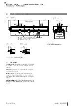
Page 35: ...Nominal length To optimally adapt the transducer to the application nominal lengths from 50 mm to 7620 mm are available Fig 3 1 BTL7 transducer construction 3 Construction and function 12 72 73 80 80...

Page 36: ...10 B Differential position Velocity with and without leading sign Speed difference 3 3 LED display Fig 3 2 LED 2 LED 1 BTL7 LED displays LED 1 Green Normal function Magnet is within the limits Red Err...

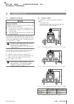
Page 37: ...ulating bushes see Fig 3 1 1 Guide the transducer into the mounting clamps 2 Attach transducer to the base using mounting screws tighten screws in the clamps with max 2 Nm 3 Insert magnet accessories...

Page 38: ...mm BTL5 P 5500 2 5 15 mm 15 mm BTL5 P 4500 1 0 1 2 mm 2 mm BTL6 A 3800 2 4 8 mm2 5 mm BTL6 A 3801 2 4 8 mm2 5 mm 1 The selected distance must stay constant over the entire measuring length 2 For optim...

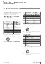
Page 39: ...6 circular plug 4 Installation and connection continued 4 4 2 Connector S115 BTL7 standard BTL7 USB Configurable Pin BTL7 S5_ _ S115 BTL7 S5_ _B S115 BTL7 S510 S115 BTL7 S510B S115 1 Clk Clk 2 Data Da...

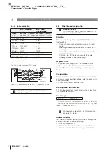
Page 40: ...nnected to connector housing Cable version On the transducer side the cable shielding is connected to the housing Magnetic fields The position measuring system is a magnetostrictive system It is impor...

Page 41: ...system manufacturer 1 Check connections for tightness and correct polarity Replace damaged connections 2 Turn on the system 3 Check measured values and adjustable parameters and readjust the transduce...

Page 42: ...erwards the transducer is ready again to receive the next clock package Clk Data TClk tv tv Clk Data MSB LSB TClk 1 2 3 4 5 n n 1 tm SSIn Clk Data TA TClk 1 fClk SSI clock period 1 SSI clock frequency...

Page 43: ...ction side with negative speeds it moves towards the connection side The controller must be set to process signed data then 6 3 Faulty SSI query Underclocking If there are too few clock edges the curr...

Page 44: ...en two clock packages and may not be confused with the SSI clock frequency Asynchronous operation During asynchronous operation the external sampling frequency is independent of the internal sampling...

Page 45: ...sducer and PC Software correctly installed Transducer connected to the power supply Magnet on transducer Output functions Position Position in the measuring range Velocity Speed of the magnet the sign...

Page 46: ...S115 S147 when attached IP67 Cable IP684 3 8 3 Supply voltage Voltage stabilized6 10 30 V DC Ripple 0 5 Vss Current draw at 24 V DC 100 mA Inrush current 500 mA 10 ms Reverse polarity protection Up t...

Page 47: ...ernal wiring Cable temperature 40 C 90 C Cable diameter Max 7 mm Permissible bending radius Fixed routing 35 mm Moved 105 mm BTL7 FA_ _ Cable material PTFE No UL approval available Cable temperature 5...

Page 48: ...ximum sampling rate for velocity output is limited to 3 3 kHz The maximum SSI clock frequency fCLK max is dependent on the cable length1 Fig 8 2 Maximum SSI clock frequency depending on the cable leng...

Page 49: ...agnet Weight Approx 28 g Housing Aluminum Slide surface Plastic BTL5 T 2814 1S 16 5 11 5 28 22 40 M5x10 Fig 9 3 Installation dimensions of BTL5 T 2814 1S magnet Weight Approx 28 g Housing Aluminum Sli...

Page 50: ...pprox 30 g Housing Plastic BTL6 A 3801 2 28 16 21 37 6 4 2 18 13 Fig 9 8 Installation dimensions of BTL6 A 3801 2 magnet Weight Approx 25 g Housing Plastic BTL5 P 4500 1 16 5 45 25 28 15 4 2 25 7 5 M5...

Page 51: ...preassembled BKS S232 PU _ _ Straight connector molded preassembled M16 8 pin Various cable lengths can be ordered e g BKS S232 PU 05 Cable length 5 m Fig 9 12 20 66 Connector BKS S232 PU _ _ BKS S233...

Page 52: ...igurable BKS S147M 00 Straight connector freely configurable M16 per IEC 130 9 7 pin Fig 9 17 62 Connector BKS S147M 00 BKS S148M 00 Angled connector freely configurable M16 per IEC 130 9 7 pin Fig 9...

Page 53: ...ray falling D Gray falling Resolution 1 1 m 3 10 m 5 40 m 7 2 m 9 0 5 m 2 5 m 4 20 m 6 100 m 8 50 m Synchronous asynchronous operation B Synchronous operation Without B Asynchronous operation Nominal...

Page 54: ...tory setting Synchronous asynchronous operation B Synchronous operation Without B Asynchronous operation Nominal length 4 digit M0500 Metric specification in mm nominal length 500 mm M0050 M7620 Const...

Page 55: ...3071 10 0 393700787 Tab 11 1 Conversion table mm to inches 1 inch 25 4 mm inch mm 1 25 4 2 50 8 3 76 2 4 101 6 5 127 6 152 4 7 177 8 8 203 2 9 228 6 10 254 Tab 11 2 Conversion table inches to mm 11 Ap...

Page 56: ...173 370 Fax 49 7158 173 691 service balluff de US Service Center USA Balluff Inc 8125 Holton Drive Florence KY 41042 Phone 859 727 2200 Toll free 1 800 543 8390 Fax 859 727 4823 technicalsupport ballu...

Page 57: ...Manual de instrucciones BTL7 S5_ _ B M_ _ _ _ P S32 S115 S147 KA_ _ FA_ _ espa ol...

Page 58: ...www balluff com...

Page 59: ...ores de posici n guiados 9 4 3 Sensores de posici n libres 10 4 4 Conexi n el ctrica 11 4 4 1 Conector S32 11 4 4 2 Conector S115 11 4 4 3 Conector S147 11 4 4 4 Conexi n de cable 12 4 5 Blindaje y te...

Page 60: ...21 9 3 Sensores de posici n libres 22 9 4 Conectores y cables 23 9 4 1 BKS S32 S33M 00 libremente confeccionable 23 9 4 2 BKS S232 S233 PU _ _ confeccionado 23 9 4 3 BKS S115 S116 PU _ _ confeccionado...

Page 61: ...ara BTL7 FA_ _ Patente estadounidense 5 923 164 La patente estadounidense se ha concedido en relaci n con este producto Con el marcado CE confirmamos que nuestros productos cumplen con los requerimien...

Page 62: ...e seguridad adecuadas El explotador es responsable de respetar las normas de seguridad locales vigentes En particular el explotador debe adoptar medidas destinadas a evitar peligros para las personas...

Page 63: ...p gina 21 Longitud nominal para adaptar de forma ptima el transductor de desplazamiento a la aplicaci n est n disponibles longitudes nominales de 50 mm a 7620 mm Fig 3 1 Transductor de desplazamiento...

Page 64: ...ocidad con y sin signo Diferencia de velocidad 3 3 Indicadores LED Fig 3 2 LED 2 LED 1 Indicadores LED BTL7 LED 1 Verde Funcionamiento normal El sensor de posici n est dentro de los l mites Rojo Error...

Page 65: ...miento en las pinzas de fijaci n 2 Fije el transductor de desplazamiento con los tornillos de fijaci n en la base apriete los tornillos en las pinzas con m x 2 Nm 3 Monte el sensor de posici n accesor...

Page 66: ...5 P 5500 2 5 15 mm 15 mm BTL5 P 4500 1 0 1 2 mm 2 mm BTL6 A 3800 2 4 8 mm2 5 mm BTL6 A 3801 2 4 8 mm2 5 mm 1 La distancia seleccionada debe permanecer constante en toda la longitud de medici n 2 Para...

Page 67: ...16 de 8 polos 4 Montaje y conexi n continuaci n 4 4 2 Conector S115 BTL7 est ndar BTL7 USB Configurable Pin BTL7 S5_ _ S115 BTL7 S5_ _B S115 BTL7 S510 S115 BTL7 S510B S115 1 Clk Clk 2 Data Data 3 Clk...

Page 68: ...e cable en el lado del transductor de desplazamiento el blindaje del cable est conectado a la carcasa Campos magn ticos El sistema de medici n de desplazamiento es un sistema magnetostrictivo Preste a...

Page 69: ...est n asentadas firmemente y tengan la polaridad correcta Sustituya las conexiones da adas 2 Conecte el sistema 3 Compruebe los valores de medici n y los par metros ajustables y en caso necesario rea...

Page 70: ...tiempo tm Luego el transductor de desplazamiento est de nuevo listo para el siguiente paquete de reloj Clk Data TClk tv tv Clk Data MSB LSB TClk 1 2 3 4 5 n n 1 tm SSIn Clk Data TA TClk 1 fClk Per od...

Page 71: ...aleja del lado de conexi n en las velocidades negativas se mueve hacia el lado de conexi n Entonces el control debe ajustarse al procesamiento de datos con signo signed 6 3 Consulta SSI err nea Subac...

Page 72: ...ncia de reloj SSI Servicio asincr nico En el servicio asincr nico la frecuencia de exploraci n externa no depende de la frecuencia de exploraci n interna del transductor de desplazamiento De este modo...

Page 73: ...corriente Sensor de posici n en transductor de desplazamiento Funciones de la salida Posici n posici n en la zona medible Velocidad velocidad del sensor de posici n el signo indica la direcci n del m...

Page 74: ...C Ondulaci n residual 0 5 Vss Consumo de corriente con 24 V DC 100 mA Corriente de pico 500 mA 10 ms Protecci n contra polarizaci n inversa Hasta 36 V alimentaci n contra GND Protecci n contra sobrete...

Page 75: ...eratura del cable 40 C 90 C Di metro del cable M x 7 mm Radio de flexi n admisible Tendido fijo 35 mm M vil 105 mm BTL7 FA_ _ Material de cable PTFE Ninguna homologaci n UL disponible Temperatura del...

Page 76: ...a con emisi n de velocidad est limitada a 3 3 kHz La frecuencia de reloj SSI m xima fCLK m x depende de la longitud del cable 1 Fig 8 2 Frecuencia de reloj SSI m xima en funci n de la longitud de cabl...

Page 77: ...minio Superficie de deslizamiento Material sint tico BTL5 T 2814 1S 16 5 11 5 28 22 40 M5x10 Fig 9 3 Medidas de montaje del sensor de posici n BTL5 T 2814 1S Peso Aprox 28 g Carcasa Aluminio Superfici...

Page 78: ...o BTL6 A 3801 2 28 16 21 37 6 4 2 18 13 Fig 9 8 Medidas de montaje del sensor de posici n BTL6 A 3801 2 Peso Aprox 25 g Carcasa Material sint tico BTL5 P 4500 1 16 5 45 25 28 15 4 2 25 7 5 M5x8 40 Fig...

Page 79: ..._ _ Conector recto recubierto confeccionado M16 8 polos Posibilidad de pedir longitudes de cable distintas p ej BKS S232 PU 05 longitud de cable 5 m Fig 9 12 20 66 Conector BKS S232 PU _ _ BKS S233 P...

Page 80: ...onector recto libremente confeccionable M16 seg n IEC 130 9 7 polos Fig 9 17 62 Conector BKS S147M 00 BKS S148M 00 Conector acodado libremente confeccionable M16 seg n IEC 130 9 7 polos Fig 9 18 18 31...

Page 81: ...ndente 9 Gray descendente D Gray descendente Resoluci n 1 1 m 3 10 m 5 40 m 7 2 m 9 0 5 m 2 5 m 4 20 m 6 100 m 8 50 m Servicio sincr nico asincr nico B servicio sincr nico Sin B servicio asincr nico L...

Page 82: ...te de f brica Servicio sincr nico asincr nico B servicio sincr nico Sin B servicio asincr nico Longitud nominal 4 cifras M0500 indicaci n m trica en mm longitud nominal 500 mm M0050 M7620 Forma constr...

Page 83: ...1 Tabla de conversi n mm pulgadas 1 pulgada 25 4 mm pulgadas mm 1 25 4 2 50 8 3 76 2 4 101 6 5 127 6 152 4 7 177 8 8 203 2 9 228 6 10 254 Tab 11 2 Tabla de conversi n pulgadas mm 11 Anexo 11 2 Placa...

Page 84: ...Fax 49 7158 173 691 service balluff de US Service Center USA Balluff Inc 8125 Holton Drive Florence KY 41042 Phone 859 727 2200 Toll free 1 800 543 8390 Fax 859 727 4823 technicalsupport balluff com C...

Page 85: ...Notice d utilisation BTL7 S5_ _ B M_ _ _ _ P S32 S115 S147 KA_ _ FA_ _ fran ais...

Page 86: ...www balluff com...

Page 87: ...4 3 Capteurs de position libres 10 4 4 Raccordement lectrique 11 4 4 1 Connecteur S32 11 4 4 2 Connecteur S115 11 4 4 3 Connecteur S147 11 4 4 4 Raccordement des c bles 12 4 5 Blindage et pose des c b...

Page 88: ...cul e BTL2 GS10 _ _ _ _ A 21 9 3 Capteurs de position libres 22 9 4 Connecteurs et c bles 23 9 4 1 BKS S32 S33M 00 assembler 23 9 4 2 BKS S232 S233 PU _ _ confectionn 23 9 4 3 BKS S115 S116 PU _ _ con...

Page 89: ...7256 1 Sauf pour BTL7 FA_ _ Brevet US 5 923 164 Le brevet am ricain a t attribu en relation avec ce produit Avec le symbole CE nous certifions que nos produits r pondent aux exigences de la directive...

Page 90: ...e les mesures de s curit ad quates Il est de la responsabilit de l exploitant de veiller ce que les dispositions locales concernant la s curit soient respect es L exploitant doit en particulier prendr...

Page 91: ...eur nominale afin de permettre une adaptation optimale du capteur de d placement l application des longueurs nominales de 50 mm 7620 mm sont disponibles Fig 3 1 Capteur de d placement BTL7 structure 3...

Page 92: ...Affichage LED Fig 3 2 LED 2 LED 1 Affichages LED du BTL7 LED 1 Vert Fonctionnement normal Le capteur de position est dans les limites Rouge Erreur Pas de capteur de position ou capteur de position ho...

Page 93: ...2 A l aide des vis de fixation fixer le capteur de d placement la base vissage de max 2 Nm dans les brides 3 Monter le capteur de position accessoire Le capteur de d placement construction profil e c...

Page 94: ...1 0 1 2 mm 2 mm BTL6 A 3800 2 4 8 mm2 5 mm BTL6 A 3801 2 4 8 mm2 5 mm 1 La distance choisie doit rester constante sur toute la longueur de mesure 2 Pour un r sultat de mesure optimal nous recommandons...

Page 95: ...4 Montage et raccordement suite 4 4 2 Connecteur S115 BTL7 Standard BTL7 USB Configurable Broche BTL7 S5_ _ S115 BTL7 S5_ _B S115 BTL7 S510 S115 BTL7 S510B S115 1 Clk Clk 2 Data Data 3 Clk Clk 4 Non u...

Page 96: ...ment le blindage de c ble doit tre reli au bo tier Champs magn tiques Le syst me de mesure de d placement est un syst me magn tostrictif Veiller ce que le capteur de d placement se trouve une distance...

Page 97: ...doivent tre respect es 1 V rifier la fixation et la polarit des raccordements Remplacer les raccordements endommag s 2 Mettre le syst me en marche 3 V rifier les valeurs mesur es et les param tres r g...

Page 98: ...uite le capteur de d placement est nouveau pr t r ceptionner la s quence d horloge suivante Clk Data TClk tv tv Clk Data MSB LSB TClk 1 2 3 4 5 n n 1 tm SSIn Clk Data TA TClk 1 fClk P riode d horloge...

Page 99: ...t de raccordement tandis que en cas de v locit s n gatives il se d place en direction du c t de raccordement La commande doit ensuite tre r gl e sur le traitement de donn es de signes 6 3 Interrogati...

Page 100: ...ge SSI Fonctionnement asynchrone Lors du fonctionnement asynchrone la fr quence d chantillonnage externe ne d pend pas de la fr quence d chantillonnage interne du capteur de d placement Ainsi en fonct...

Page 101: ...l alimentation secteur Le capteur de position doit se trouver sur le capteur de d placement Fonctions de la sortie Position position dans la plage de mesure V locit v locit du capteur de position le...

Page 102: ...CC Ondulation r siduelle 0 5 Vss Consommation de courant 24 V CC 100 mA Courant de cr te au d marrage 500 mA 10 ms Protection contre l inversion de polarit Jusqu 36 V alimentation la masse Protection...

Page 103: ...c ble 40 C 90 C Diam tre de c ble Max 7 mm Rayon de courbure autoris Pose fixe 35 mm Pose mobile 105 mm BTL7 FA_ _ Mat riau du c ble PTFE Aucune homologation UL disponible Temp rature de c ble 55 C 2...

Page 104: ...imale pour l mission de v locit est limit e 3 3 kHz La fr quence d horloge SSI maximale fCLK max d pend de la longueur du c ble1 Fig 8 2 Fr quence d horloge SSI en fonction de la longueur de c ble fA...

Page 105: ...oids Env 28 g Bo tier Aluminium Surface de glissement Plastique BTL5 T 2814 1S 16 5 11 5 28 22 40 M5x10 Fig 9 3 Dimensions de montage du capteur de position BTL5 T 2814 1S Poids Env 28 g Bo tier Alumi...

Page 106: ...e BTL6 A 3801 2 28 16 21 37 6 4 2 18 13 Fig 9 8 Dimensions de montage du capteur de position BTL6 A 3801 2 Poids Env 25 g Bo tier Plastique BTL5 P 4500 1 16 5 45 25 28 15 4 2 25 7 5 M5x8 40 Fig 9 9 Di...

Page 107: ...extrud confectionn M16 8 p les Diff rentes longueurs de c ble disponibles p ex BKS S232 PU 05 longueur de c ble 5 m Fig 9 12 20 66 Connecteur BKS S232 PU _ _ BKS S233 PU _ _ Connecteur coud extrud co...

Page 108: ...S147M 00 Connecteur droit assembler M16 selon IEC 130 9 7 p les Fig 9 17 62 Connecteur BKS S147M 00 BKS S148M 00 Connecteur coud assembler M16 selon IEC 130 9 7 p les Fig 9 18 18 31 37 2 20 6 8 54 Co...

Page 109: ...ssant D Gray d croissant R solution 1 1 m 3 10 m 5 40 m 7 2 m 9 0 5 m 2 5 m 4 20 m 6 100 m 8 50 m Fonctionnement synchrone asynchrone B fonctionnement synchrone Sans B fonctionnement asynchrone Longue...

Page 110: ...ent synchrone asynchrone B fonctionnement synchrone Sans B fonctionnement asynchrone Longueur nominale 4 chiffres M0500 donn e m trique en mm longueur nominale 500 mm M0050 M7620 Forme de construction...

Page 111: ...11 1 Conversion mm pouce 1 pouce 25 4 mm pouce mm 1 25 4 2 50 8 3 76 2 4 101 6 5 127 6 152 4 7 177 8 8 203 2 9 228 6 10 254 Tab 11 2 Conversion pouce mm 11 Annexe 11 2 Plaque signal tique 1 Symbolisat...

Page 112: ...370 Fax 49 7158 173 691 service balluff de US Service Center USA Balluff Inc 8125 Holton Drive Florence KY 41042 Phone 859 727 2200 Toll free 1 800 543 8390 Fax 859 727 4823 technicalsupport balluff...

Page 113: ...Manuale d uso BTL7 S5_ _ B M_ _ _ _ P S32 S115 S147 KA_ _ FA_ _ italiano...

Page 114: ...www balluff com...

Page 115: ...ore di posizione libero 10 4 4 Collegamento elettrico 11 4 4 1 Connettore S32 11 4 4 2 Connettore S115 11 4 4 3 Connettore S147 11 4 4 4 Collegamento cavo 12 4 5 Schermatura e posa dei cavi 12 5 Messa...

Page 116: ...osizione libero 22 9 4 Connettori e cavi 23 9 4 1 BKS S32 S33M 00 confezionabile liberamente 23 9 4 2 BKS S232 S233 PU _ _ confezionato 23 9 4 3 BKS S115 S116 PU _ _ confezionato 24 9 4 4 BKS S147 S14...

Page 117: ...ogazione UL1 File No E227256 1 Non per BTL7 FA_ _ Brevetto statunitense 5 923 164 Il brevetto statunitense stato rilasciato in relazione a questo prodotto Il marchio CE la conferma che i nostri prodot...

Page 118: ...pericoli e di adottare misure di sicurezza adeguate Il gestore ha la responsabilit di far rispettare le norme di sicurezza vigenti localmente In particolare il gestore deve adottare provvedimenti tali...

Page 119: ...i da pagina 21 Lunghezza nominale per adattare in maniera ottimale il trasduttore di posizione all applicazione sono disponibili le lunghezze nominali da 50 mm a 7620 mm Fig 3 1 Trasduttore di posizio...

Page 120: ...zione Velocit con e senza segni Variazione di velocit 3 3 Display LED Fig 3 2 LED 2 LED 1 Display LED BTL7 LED 1 Verde Funzionamento normale Il datore di posizione si trova entro i limiti Rosso Errore...

Page 121: ...zione nelle staffe di fissaggio 2 Fissare il trasduttore di posizione sulla base con le viti di fissaggio serrare le viti nelle staffe o nelle fascette con max 2 Nm 3 Montare il datore di posizione ac...

Page 122: ...TL5 P 3800 2 0 1 4 mm 2 mm BTL5 P 5500 2 5 15 mm 15 mm BTL5 P 4500 1 0 1 2 mm 2 mm BTL6 A 3800 2 4 8 mm2 5 mm BTL6 A 3801 2 4 8 mm2 5 mm 1 La distanza selezionata deve rimanere costante per l intera l...

Page 123: ...8 poli 4 Montaggio e collegamento continua 4 4 2 Connettore S115 BTL7 Standard BTL7 USB Configurable Pin BTL7 S5_ _ S115 BTL7 S5_ _B S115 BTL7 S510 S115 BTL7 S510B S115 1 Clk Clk 2 Data Data 3 Clk Cl...

Page 124: ...del connettore sull intera superficie Versione con cavo sul lato del trasduttore di posizione la schermatura del cavo collegata con il corpo Campi magnetici Il sistema di misura della corsa un sistem...

Page 125: ...re che i collegamenti siano fissati saldamente e che la loro polarit sia corretta Sostituire i collegamenti danneggiati 2 Attivare il sistema 3 Controllare i valori misurati e i parametri regolabili e...

Page 126: ...e di posizione pronto alla ricezione del prossimo pacchetto clock Clk Data TClk tv tv Clk Data MSB LSB TClk 1 2 3 4 5 n n 1 tm SSIn Clk Data TA TClk 1 fClk Periodo clock SSI frequenza clock 1 SSI TA 1...

Page 127: ...lato collegamento mentre in caso di velocit negativa si muove verso il lato collegamento L unit di controllo deve essere quindi impostata sull elaborazione dei dati segnalati 6 3 Interrogazione SSI er...

Page 128: ...sere scambiata con la frequenza clock SSI Funzionamento asincrono Nel funzionamento asincrono la frequenza di scansione esterna indipendente dalla frequenza di scansione interna del trasduttore di pos...

Page 129: ...tamente Trasduttore di posizione collegato all alimentazione elettrica Datore di posizione sul trasduttore di posizione Funzioni dell uscita Posizione posizione nel campo di misura Velocit velocit del...

Page 130: ...10 30 V DC Ondulazione residua 0 5 Vss Corrente assorbita con 24 V DC 100 mA Corrente massima di avviamento 500 mA 10 ms Protezione contro l inversione di polarit fino a 36 V alimentazione verso GND P...

Page 131: ...Temperatura cavo 40 C 90 C Diametro del cavo max 7 mm Raggio di curvatura consentito Posa fissa 35 mm Mobile 105 mm BTL7 FA_ _ Materiale cavo PTFE Nessuna omologazione UL disponibile Temperatura cavo...

Page 132: ...uscit di velocit limitata a 3 3 kHz La frequenza massima di impulso SSI fCLK max dipende dalla lunghezza della linea1 Fig 8 2 Frequenza di impulso massima SSI in base alla lunghezza della linea fA max...

Page 133: ...upporto alluminio Superficie di scorrimento materiale plastico BTL5 T 2814 1S 16 5 11 5 28 22 40 M5x10 Fig 9 3 Dimensioni di ingombro datore di posizione BTL5 T 2814 1S Peso circa 28 g Supporto allumi...

Page 134: ...materiale plastico BTL6 A 3801 2 28 16 21 37 6 4 2 18 13 Fig 9 8 Dimensioni di ingombro datore di posizione BTL6 A 3801 2 Peso circa 25 g Supporto materiale plastico BTL5 P 4500 1 16 5 45 25 28 15 4 2...

Page 135: ...confezionato BKS S232 PU _ _ Connettore diritto incorporato confezionato M16 a 8 poli possibile ordinare diverse lunghezze del cavo p es BKS S232 PU 05 lunghezza cavo 5 m Fig 9 12 20 66 Connettore BKS...

Page 136: ...Connettore a spina diritto confezionabile liberamente M16 secondo IEC 130 9 a 7 poli Fig 9 17 62 Connettore BKS S147M 00 BKS S148M 00 Connettore ad angolo confezionabile liberamente M16 secondo IEC 1...

Page 137: ...nte 9 Gray discendente D Gray discendente Risoluzione 1 1 m 3 10 m 5 40 m 7 2 m 9 0 5 m 2 5 m 4 20 m 6 100 m 8 50 m Funzionamento sincrono asincrono B funzionamento sincrono senza B funzionamento asin...

Page 138: ...azioni di fabbrica Funzionamento sincrono asincrono B funzionamento sincrono senza B funzionamento asincrono Lunghezza nominale a 4 cifre M0500 indicazione metrica in mm lunghezza nominale 500 mm M005...

Page 139: ...abella di conversione mm pollici 1 pollice 25 4 mm pollici mm 1 25 4 2 50 8 3 76 2 4 101 6 5 127 6 152 4 7 177 8 8 203 2 9 228 6 10 254 Tab 11 2 Tabella di conversione pollici mm 11 Appendice 11 2 Tar...

Page 140: ...3 370 Fax 49 7158 173 691 service balluff de US Service Center USA Balluff Inc 8125 Holton Drive Florence KY 41042 Phone 859 727 2200 Toll free 1 800 543 8390 Fax 859 727 4823 technicalsupport balluff...

Reviews: