8 | Baker Hughes
Copyright 2021 Baker Hughes Company. All rights reserved.
Gaskets
Gasket seating surfaces must be free of dents, scratches,
corrosion, or other types of damage. Clean mating surfaces as
required and replace any non-conforming parts. Spiral wound
gaskets (Items 25, 26 & 27) must always be replaced after
disassembly.
Seal Rings
Seal rings (9), back-up rings (28), retaining rings (23), and
conical springs (14) should be inspected periodically. It is
recommended to routinely replace these parts, but they may
be re-used if they are free from scratches, erosion, corrosion,
or other damage.
Note: Compressed graphite seal rings must be replaced
each time the plug is removed from the valve.
Metal Seal
For the two piece bonnet configurations:
Prior to reassembly, the metal seal (6) should be inspected for
cracks or signs of wear. The metal seal can be reused if it is
free from scratches, erosion, corrosion, or any other type of
damage.
If slight wear exists on the metal seal, a new layer of coating
should be re-applied to the original condition by the factory
or a Masoneilan Authorized Repair Center (
MARC
™
). For
emergency repairs in the field, the metal seal may be coated
with a molybdenum disulfide based spray on lubricant such as
MolyKote
®
.
Prior to reassembly of the valve, inspect the inside of the valve
body around the area where the metal seal seats. It is common
to find slight ridges or depressions from where the seal was
originally seated. During initial assembly these depressions aid
in the sealing of the valve, however these areas can become
leak paths during reassembly if the surface is not restored to its
original finish as described below.
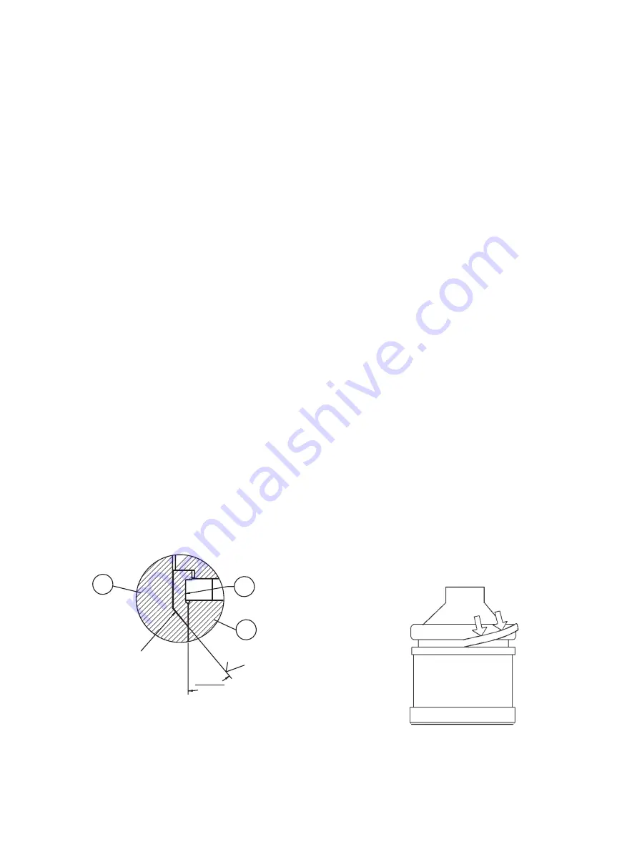
To prevent this potential leakage, machine the seating angle of
the bonnet at 40 degrees by approximately 0.1 inches (2.5 mm)
deep, thus causing the metal seal to seat further down inside
the valve body (on a new undeformed surface). Refer to Figure
7 for details.
Figure 7 - Bonnet Seating Angle Details
(see page 12, detail B)
Figure 8 - Installing Seal Ring
Conical Springs
For Models that use a conical spring design, always inspect the
body bore surface adjacent to where the conical spring (14) is
seated. If this surface has been deformed or if there is a groove
where the seal seats, the surface should be cleaned and honed
prior to reassembling the valve.
If the refinishing procedure is unsuccessful, the factory should
be consulted for further instructions.
Valve Reassembly
Pinning the Valve Plug
The valve plug assembly consists of a stem (7) that is threaded
into the valve plug (8). To secure this assembly, the stem (7) is
then pinned (24) and tack welded to the valve plug (8).
If the valve plug (8) or stem (7) needs to be replaced, an entire
assembly should be purchased from the factory to ensure
product strength and integrity. Re-machining of these parts
in the field can seriously impair the mechanical strength and
integrity of the valve plug stem assembly.
Seal Ring Assembly
Model 724XX (Auxiliary Pilot Plug) and
725XX (Metal Seal Ring)
1. To insert the seal ring in the valve plug groove, place it over
the conical top of the plug, then push down evenly from all
sides until the ring slips into the groove. See Figure 8.
Note: These valves may also be equipped with a second-
ary metal seal and elastomeric back-up ring located on the
lower area of the plug near the seating surface.
2. Install the back-up ring (28) onto the plug using care not
to damage the ring on any sharp surfaces. The back-up
ring does not require lubrication, however, a light coating of
compatible lubricant will help install the seal.
3. Install the seal ring (9) over the back-up ring (28).
Note: When the plug assembly is installed into the cage
bore, the lead in angle of the cage will compress the ring
into place. If the seal ring is not compressed a ring com-
pression tool may be required for proper installation.
6
AND BURRS
EDGE MUST BE
FREE FROM NICKS
Ra
0.8
40°30'
39°30'
2
1
Pushing
Direction


