24 |
Baker Hughes
© 2020 Baker Hughes Company. All rights reserved.
XIV. Setting and Testing (Cont.)
Figure 14
Gag safety valve during
ring adjustments to
avoid possible severe
personal injury or
death.
pressure of the safety valve, it is
recommended the valve be replaced
with a blind flange during hydrostatic
testing.
Probably the most common source of
safety valve trouble is overgagging.
During hydrostatic testing, and during
safety valve setting, gags should be
applied only hand tight. During setting,
overgagging could cause damage
to the seating surface and result in
leakage. In applying gags, remember
that the valve spring will hold the valve
closed against its set pressure. The
additional gag load applied should
be only enough to insure that the
valves do not lift at the expected over-
pressure.
Gags should never be applied when
the boiler is cold. The spindle of the
safety valve expands considerably with
the temperature increase as pressure
is raised. If it is not free to expand with
this temperature change, the spindle
may be damaged.
Boiler pressure should be increased
to 80% of the pressure of the low set
valve before applying the gags.
Hand tighten the gags of drum and
superheater valves with only a light
force.
B.2 Application of Test
Gags (All Pressures)
1. Refer to Figures 1 & 2 on Section
VIII. Remove lever pin and lever.
Then loosen cap screw and remove
cap.
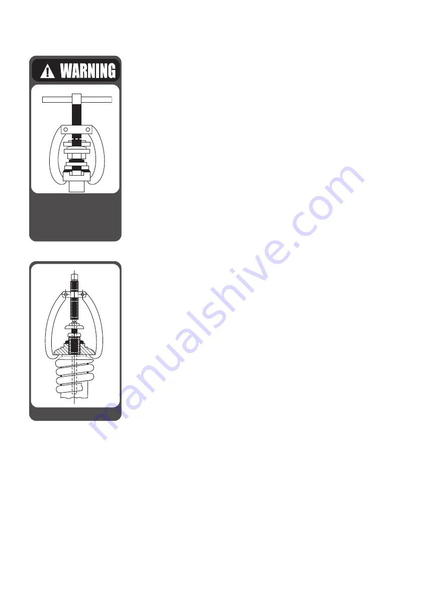
2. Center the test gag screw in the
exposed end of the spindle and
hook the legs of gag under the
sides of the yoke as shown in
Figure 14.
Do not apply the gag load until
the boiler hydrostatic pressure
is equal to 80% of the pressure
to which the low set valve is
adjusted.
3. Apply the gag load by turning the
gag screw clockwise. If the gag on
any valve has not been tightened
sufficiently, the valve will leak.
If this occurs, the hydrostatic
test pressure should be reduced
until the valve becomes tight and
then the gag should be tightened
still further.
This procedure must be followed
exactly since it is very difficult to
stop the leak by additional gagging
once it has started. Any attempt
to pinch off the leakage through
the valve without first lowering the
hydrostatic pressure may result in
damage to the valve seats.
4. After the hydrostatic test is
completed, the gags should be
removed when the hydrostatic
pressure has been reduced to 85%
to 90% of the low set valve.
Under no circumstances should
the gags be left on valves with
no hydrostatic pressure on the
system.
C. Presetting the
Adjusting Rings
If the correct position of the adjusting
rings (as measured in the disassembly
procedure (see Section X) is not
known, the valve adjusting rings may
be positioned using the information in
Table 9.
The lower ring may be positioned by
turning the lower adjusting ring up until
it contacts the disc. After choosing
the appropriate orifice size, turn the
adjusting ring down the corresponding
number of notches listed in the “Lower
Ring” column. Then, replace the
adjusting ring pin. The adjusting ring
must be free to move both directions,
but not rotate.
The upper ring may be positioned by
turning the upper adjusting ring down
towards the nozzle bushing, until it


