20 |
Baker Hughes
© 2020 Baker Hughes Company. All rights reserved.
1.
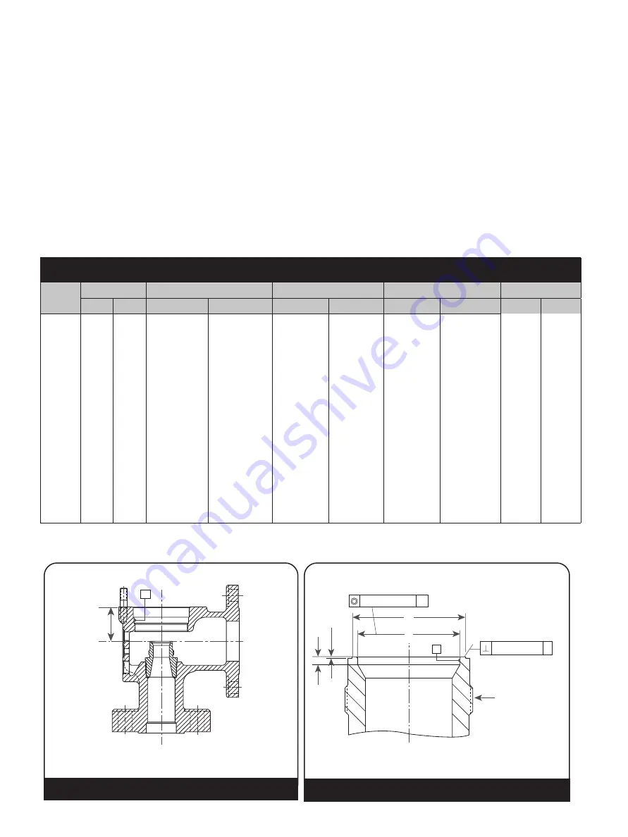
Seat profile must be reestablished when Dimension (E) is .020” (0.51 mm) for Orifice F - N, or .030” (0.76 mm) for P – Q
Orifice. Once (Z max.) has been reached, discard. Do not remachine the head flange to reestablish (Z).
Table 7: Base and Seat Bushing Assembly Rework/Inspection Dimensions
Orifice
B max
C
E
1
F
Z max
in.
mm
in.
mm
in.
mm
in.
mm
in.
mm
F
.740 18.80
.839
+
-
.001
.002
21.31
+
-
0.03
0.05
.028
+
-
.002
.003
0.71
+
-
0.05
0.08
.113
+
-
.002
.003
2.87
+
-
0.05
0.08
2.083
52.91
G
.947 24.05 1.069
+
-
.001
.002
27.15
+
-
0.03
0.05
.028
+
-
.002
.003
0.71
+
-
0.05
0.08
.089
+
-
.002
.003
2.26
+
-
0.05
0.08
2.083
52.91
H
1.182 30.02 1.353
+
-
.001
.002
34.37
+
-
0.03
0.05
.028
+
-
.002
.003
0.71
+
-
0.05
0.08
.103
+
-
.002
.003
2.62
+
-
0.05
0.08
2.203
55.96
J
1.513 38.43 1.677
+
-
.002
.001
42.60
+
-
0.05
0.03
.028
+
-
.002
.003
0.71
+
-
0.05
0.08
.126
+
-
.002
.003
3.20
+
-
0.05
0.08
2.271
57.68
K
1.809 45.95 1.999
+
-
.001
.002
50.77
+
-
0.03
0.05
.028
+
-
.002
.003
0.71
+
-
0.05
0.08
.145
+
-
.002
.003
3.68
+
-
0.05
0.08
2.645
67.18
L
2.248 57.10 2.479
+
-
.001
.002
62.97
+
-
0.03
0.05
.028
+
-
.002
.003
0.71
+
-
0.05
0.08
.174
+
-
.002
.003
4.42
+
-
0.05
0.08
3.083
78.31
M
2.523 64.08 2.779
+
-
.001
.002
70.59
+
-
0.03
0.05
.028
+
-
.002
.003
0.71
+
-
0.05
0.08
.192
+
-
.002
.003
4.88
+
-
0.05
0.08
3.458
87.83
N
2.773 70.43 3.073
+
-
.003
.003
78.05
+
-
0.08
0.08
.028
+
-
.002
.003
0.71
+
-
0.05
0.08
.206
+
-
.002
.003
5.23
+
-
0.05
0.08
3.958
100.53
P
3.364 85.45 3.718
+
-
.002
.002
94.44
+
-
0.05
0.05
.039
+
-
.002
.003
0.99
+
-
0.05
0.08
.245
+
-
.002
.003
6.22
+
-
0.05
0.08
4.458
113.23
Q
4.424 112.37 4.818
+
-
.001
.002
122.38
+
-
0.03
0.05
.039
+
-
.002
.003
0.99
+
-
0.05
0.08
.312
+
-
.002
.003
7.92
+
-
0.05
0.08
5.333
135.46
H
X
.001” (0.03 mm) B
B
J
C
E
F
B
Ø.005” (0.13 mm)
Z
H
Figure 13: Base and Seat Bushing Assembly
Figure 12: Base and Seat Bushing Assembly
XII. Inspection and Part Replacement (Cont.)
4. Adjusting rings:
If damage is present on the lower surface of the
upper adjusting ring, or on the upper surfaces of
the lower adjusting ring, the damaged part must be
replaced. Thread damage may also be a cause for
replacement, if it prevents adjustments when the
valve is heated.
5. Bushing Seat:
Seat bushings are normally treated as part
of the valve body and should be machined
when necessary, inside the valve body (see
Seat Bushing Machining Instructions, Section
XI.B). When the “E” dimensions are reduced by
machining or lapping to a minimum given in Table
7, the valve seat bushing should be remachined
to the given dimensions. The bushing seat can
be remachined in 1811 Safety Valves until the
limiting dimensions are reached. See instructions
concerning the “Z” dimension in Table 7. The
bushing seat must be lapped to a mirror finish to
determine if they are flat and free of nicks, cuts
and scratches (see Section XI.C for Lapping
Instructions).


