background image

INSTALLATION

I-E96-416B   

2 - 7

Power Wiring

This section explains how to connect power wiring. The NTAI05
unit has two fast-on connections for power and I/O common.
Make power connections to the termination unit after it is
mounted in the NFTP01 termination panel. Make sure cabinet
and I/O power are turned off before connecting ground and
power wiring.

Use 14 gauge wire for power wiring. To connect power to the
termination unit in a system using modular power supplies:

1. Attach a 14 AWG wire from the 24 VDC supply to
the E1 fast-on connector.

2. Attach a 14 AWG wire from the DC bus bar at the bottom of
the cabinet to the E2 fast-on connector.

The NTAI05 unit is ready for operation if:

1. The circuit board is mounted in the field termination panel.

2. The dipshunts are cut and verified.

3. All required cables are connected to the termination unit.

4. All required field wires are connected to the termination
unit and have been verified.

5. Power is connected and applied to the termination unit.

Summary of Contents for infi 90 NTAI05

Page 1: ... Process Control and Automation Solutions from Elsag Bailey Group E96 416 Analog Input Termination Unit NTAI05 ...

Page 2: ...MENTS ÉLECTRONIQUES SONT SENSIBLES AUX PERTURBATIONS PAR FRÉQUENCE RADIO DES PRÉCAUTIONS DEVRONT ÊTRE PRISES LORS DE L UTILISATION DU MATÉ RIEL DE COMMUNICATION PORTATIF LA PRUDENCE EXIGE QUE LES PRÉCAUTIONS À PRENDRE DANS CE CAS SOIENT SIGNALÉES AUX ENDROITS VOULUS DANS VOTRE USINE PERTURBATIONS DU PROCÉDÉ L ENTRETIEN DOIT ÊTRE ASSURÉ PAR UNE PERSONNE QUALIFIÉE EN CONSIDÉRANT L ASPECT SÉCURITAIRE...

Page 3: ... or the IMASI02 and NASI02 Analog Slave Input Mod ules or the IMFBS01 Field Bus Slave Module with two wire transmitters This manual explains how to install and use the NTAI05 termi nation unit in the INFI 90 system It contains sections that describe setup and cabling The appendices contain data about the IMASM01 IMFBS01 and IMASI02 modules Registered trademark of Elsag Bailey Process Automation ...

Page 4: ... 5 1 Original A 1 Original B 1 through B 2 Original C 1 through C 2 Original Index 1 Original When an update is received insert the latest changed pages and dispose of the super seded pages NOTE On an update page the changed text or table is indicated by a vertical bar in the outer mar gin of the page adjacent to the changed area A changed figure is indicated by a vertical bar in the outer margin ...

Page 5: ...fore installing or removing a cable assigned to that slot Failure to do so could result in damage to the module p 2 5 4 1 We strongly recommend that you turn off cabinet power before doing any termination unit wiring Failure to do so could result in equipment damage Do not apply power until you verify all wire con nections p 2 6 If input or output circuits are a shock hazard after disconnecting sy...

Page 6: ...mplacement Un manquement à cette procédure pourrait endom mager le module p 2 5 4 1 Il est fortement recommande de debracher l alimentation electrique du cabinet avant d effectuer tout connexion aux cartes de raccord ment du chassis Des dommages aux equipments pourraient surve nir dans le cas contraire Ne pas rebrancher l alimentation avant que toutes les connexions aient ete verifiees p 2 6 Si de...

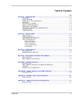
Page 7: ...TION 2 2 Dipshunt Settings 2 2 Physical Installation 2 2 Cable Connections 2 4 Terminal Block Wiring 2 5 Power Wiring 2 7 SECTION 3 MAINTENANCE 3 1 INTRODUCTION 3 1 MAINTENANCE SCHEDULE 3 1 SECTION 4 REPAIR REPLACEMENT PROCEDURES 4 1 INTRODUCTION 4 1 REPLACEMENT PROCEDURES 4 1 SECTION 5 SUPPORT SERVICES 5 1 INTRODUCTION 5 1 REPLACEMENT PARTS AND ORDERING INFORMATION 5 1 TRAINING 5 1 TECHNICAL DOCU...

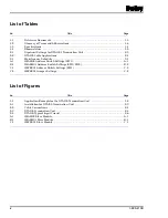
Page 8: ...MASI02 Address Switch Settings SW1 A 1 B 1 IMASM01 Address Switch Settings SW1 SW2 B 2 C 1 IMFBS01 Address Switch Settings SW1 C 2 C 2 IMFBS01 Jumper Settings C 2 List of Figures No Title Page 1 1 Application Example for the NTAI05 Termination Unit 1 2 2 1 Installation for NTAI05 Termination Unit 2 3 2 2 Cable Connections 2 4 2 3 NTAI05 Termination Unit 2 4 2 4 NTAI05 Typical Input Circuit 2 6 A 1...

Page 9: ...reading and understanding this manual TERMINATION UNIT DESCRIPTION The NTAI05 unit is a single printed circuit board that mounts to an NFTP01 Field Termination Panel The termination unit TU has one cable connector for signals P1 carries the inputs to the slave module through the cable The terminal blocks for field wiring are on the termination unit The dipshunts on the NTAI05 unit set the input ty...

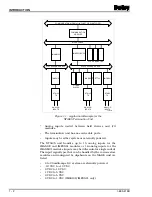
Page 10: ... be handled by the various slave modules and configured by dipshunts on the NIAI05 unit are listed 4 to 20 milliamps DC system or externally powered 10 VDC to 10 VDC 0 VDC to 10 VDC 1 VDC to 5 VDC 0 VDC to 5 VDC 0 VDC to 1 VDC IMASI02 IMFBS01 only Figure 1 1 Application Example for the NTAI05 Termination Unit COMMUNICATION HIGHWAY INFI NET OR PLANT LOOP MODULE BUS IMAMM03 IMMFP01 02 03 NTAI05 TU N...

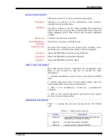
Page 11: ...lave Input Module Appendix B Shows the IMASM01 Analog Slave Module Appendix C Shows the IMFBS01 Field Bus Slave HOW TO USE THIS MANUAL Read this manual before connecting the termination unit Refer to the sections in this list as needed for more information 1 Read the installation section before connecting the NTAI05 unit 2 Refer to Appendix A B or C for the slave module connected to the terminatio...

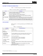
Page 12: ... troubleshooting TU Termination unit Provides input output connection between plant equipment and the INFI 90 process modules The termination unit mounts to a field termination panel Table 1 3 Specifications Property Characteristic Value Power Requirements 24 VDC 20 mA per input Mounting Mounts in the NFTP01 Field Termination Panel Environmental Electromagnetic Radio Frequency Interference Ambient...

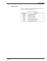
Page 13: ...th the NTAI05 termination unit Table 1 4 Nomenclature Nomenclature Description IMASI02 Analog Input Slave Module IMASM01 Analog Slave Module IMFBS01 Field Bus Slave Module NFTP01 Field Termination Panel NKTU01 Cable Termination Unit PVC NKTU11 Cable Termination Unit non PVC STT02 Smart Transmitter Terminal ...

Page 14: ...atic safe practices when working with modules 1 Use Static Shielding Bags Keep the modules in the static shielding bag until they are ready to be used in the sys tem Save the bag for future use 2 Ground Bags Before Opening Before opening a bag con taining an assembly with CMOS devices touch it to the equip ment housing or ground to equalize charges 3 Avoid Touching Circuitry Handle assemblies by t...

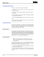
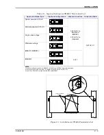
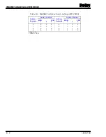
Page 15: ...t Settings The dipshunts select the input type to match the device con nected to the termination unit Each channel is independent The selections include voltage or current input differential or single ended system or externally powered Set the dipshunts according to the instructions for the slave and input type used Refer to Table 2 1 for an example of dipshunts Physical Installation NOTE This sec...

Page 16: ...ngs are shown for IMASM01 IMASI02 and IMFBS01 in point to point mode 2 Starp one connects pin one to pin 16 strap two connects pin two to pin 15 etc 3 Input 16 on NTAI05 is not used with IMASI02 and IMFBS01 1 16 2 15 3 14 4 13 5 12 6 11 7 10 8 9 1 16 2 15 3 14 4 13 5 12 6 11 7 10 8 9 1 16 2 15 3 14 4 13 5 12 6 11 7 10 8 9 1 16 2 15 3 14 4 13 5 12 6 11 7 10 8 9 1 16 2 15 3 14 4 13 5 12 6 11 7 10 8 ...

Page 17: ...PUT 16 NOT USED WITH IMASI02 AND IMFBS01 DIPSHUNT RECEPTACLES XU1 XU8 P1 CONNECTOR FOR NKTU01 11 CABLE DIPSHUNT RECEPTACLE XU17 E2 COMMON E1 24 VDC 8 7 6 5 4 3 2 1 16 15 TB4 13 14 8 8 8 7 7 7 6 6 6 5 5 5 4 4 4 3 3 3 2 2 2 1 1 1 12 8 4 11 7 3 TB3 TB2 TB1 9 5 1 10 6 2 T00586A 9 8 10 7 15 2 14 3 13 4 12 5 11 6 16 1 XU16 9 8 10 7 15 2 14 3 13 4 12 5 11 6 16 1 XU12 9 9 8 8 10 10 7 7 15 15 2 2 14 14 3 3...

Page 18: ...with the front of the rack Terminal Block Wiring Connect the wiring to the termination unit terminals from the input devices sensing the process Input devices may be BC BCN series Bailey Controls Pressure Transmitters EQ EQN series Bailey Controls Temperature Transmitters pH series Bailey Controls pH TBN Transmitters or any conventional transmitter See Figure 2 4 for an example of an NTAI05 input ...

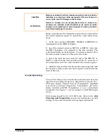
Page 19: ...avant d effectuer tout connexion aux cartes de raccordment du chassis Des dommages aux equipments pourraient survenir dans le cas contraire Ne pas rebrancher l alimentation avant que toutes les connexions aient ete veri fiees CAUTION If input or output circuits are a shock hazard after disconnect ing system power at the power entry panel then the door of the cabinet containing these externally pow...

Page 20: ...ower to the termination unit in a system using modular power supplies 1 Attach a 14 AWG wire from the system 24 VDC supply to the E1 fast on connector 2 Attach a 14 AWG wire from the DC bus bar at the bottom of the cabinet to the E2 fast on connector The NTAI05 unit is ready for operation if 1 The circuit board is mounted in the field termination panel 2 The dipshunts are cut and verified 3 All re...

Page 21: ...enance schedule MAINTENANCE SCHEDULE Execute the tasks in Table 3 1 at the specified intervals Table 3 1 Maintenance Schedule Task Interval Clean and tighten all power and grounding connections Every 6 months or during plant shutdown whichever occurs first Use a static safe vacuum cleaner to remove dust from Field termination panel Termination units ...

Page 22: ...odule mounting unit slots before installing or removing a cable assigned to that slot Failure to do so could result in damage to the module ATTENTION Retirer le module de son emplacement dans le chassis de montage des modules avant d installer ou de retirer un câble assigne a cet emplacement Un manquement à cette procédure pourrait endommager le module CAUTION If input or output circuits are a sho...

Page 23: ...o that no pins are bent over 8 Insert the tabs of the replacement circuit board into the proper slots of the field termination panel stand off and slide the circuit board into position 9 Secure the termination unit circuit board to the field termi nation panel with the two number 10 screws 10 Connect all field wiring removed in Step 3 and verify con nections 11 Connect the system I O power and gro...

Page 24: ... number and quantity 2 Model and serial numbers if applicable 3 Bailey instruction manual number page number and refer ence figure that identifies the part Order parts without commercial descriptions from the nearest Bailey Controls Company sales office TRAINING Bailey Controls has a modern training facility available for training your personnel On site training is also available Con tact a Bailey...

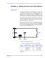
Page 25: ...rsonnel installing the NTAI05 termination unit Figure A 1 shows the termination unit dipshunt settings for the IMASI02 slave Table A 1 lists the address switch settings Be sure to check the dipswitches before installing the IMASI02 slave Refer to the IMASI02 instruction for more detailed infor mation to install and configure the slave Figure A 1 IMASI02 Slave Module EDGE CONNECTORS ADDRESS SWITCH ...

Page 26: ...is information is provided as a quick reference guide for person nel installing the NTAI05 termination unit Figure B 1 shows the termination unit dipshunt settings for the IMASM01 slave Table B 1 lists the address switch settings Be sure to check the dipswitches before installing the IMASM01 slave Refer to the IMAMM03 IMASM01 IMASM02 IMASM03 and IMASM04 instruction for more detailed informa tion t...

Page 27: ...96 416B Table B 1 IMASM01 Address Switch Settings SW1 SW2 Address Example Switch Position Address Example Switch Position MSB LSB 1 2 3 MSB LSB 1 2 3 0 1 2 3 0 0 0 0 0 1 0 1 0 0 1 1 4 5 6 7 1 0 0 1 0 1 1 1 0 1 1 1 OPEN OFF 1 CLOSED ON 0 ...

Page 28: ...5 2 3 Instruction content 1 3 Intended user 1 1 M Maintenance schedule 3 1 N Nomenclature 1 5 NTAI05 termination unit 2 4 Cable connections 2 4 Input circuit 2 6 O Overview 1 1 R Reference documents 1 3 Replacement parts and ordering 5 1 Replacement parts ordering information 5 1 Replacement procedures 4 1 S Setup installation 2 2 Cable connections 2 4 Dipshunt settings 2 2 Physical installation 2...

Page 29: ... 8756 ASIA PACIFIC 152 Beach Road Gateway East 20 04 Singapore 189721 Telephone 65 391 0800 Telefax 65 292 9011 EUROPE AFRICA MIDDLE EAST Via Puccini 2 16154 Genoa Italy Telephone 39 10 6582 943 Telefax 39 10 6582 941 GERMANY Graefstrasse 97 D 60487 Frankfurt Main Germany Telephone 49 69 799 0 Telefax 49 69 799 2406 Form I E96 416B Litho in U S A 992 Copyright 1992 by Elsag Bailey Process Automati...

Reviews: