25
25
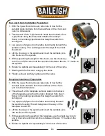
7. Starting with the first cam, snug up the cams.
8. Finally, recheck and fully tighten all of the cams.
OPERATING CONTROLS
•
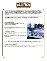
The main disconnect on the electrical cabinet is
the Power On switch.
•
Green indicator light (A) will be lit when machine
is powered up.
•
Two position switch (B) to start and stop coolant
pump.
•
Pressing the E-Stop Button (C) will immediately
stop the machine in the event of incorrect
operation or a dangerous situation. Twist the
emergency stop button clockwise (cw) to reset.
Spindle Speeds
IMPORTANT:
Never change spindle speeds
while the motor or spindle is in motion.
•
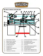
The speed of the spindle is set by the position of
the two speed control handles.
Handle (13) selects between Low range (L) and
High range (H).
Handle (12) selects between the available speeds within each range.
•
Spindle speed is measured in RPM (revolutions per minute) The following spindle speeds
are possible: (L) 70, 115, 190, 300, (H) 460, 755, 1255, and 2000 RPM.
CAUTION:
Always wear proper eye protection with side shields, safety
footwear, and leather gloves to protect from burrs and sharp edges.
When handling large heavy materials make sure they are properly supported.
A B C
13
12
Summary of Contents for PL-1340E-1.0
Page 48: ...45 45 ELECTRICAL DIAGRAM...


