24
24
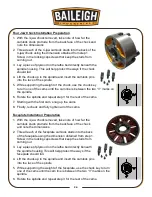
Four Jaw Chuck Installation Preparation
1. With the 3-jaw chuck removed, take note of how far the
camlock studs protrude from the back face of the chuck and
note the dimensions.
2. Thread each of the 4-jaw camlock studs into the back of the
4-jaw chuck using the dimension obtained from step 1.
Screw in the locking capscrews that keep the studs from
coming out.
3. Lay a piece of plywood on the lathe bed directly beneath the
spindle housing. This will help protect the ways if the chuck
should fall.
4. Lift the chuck up to the spindle and insert the camlock pins
into the face of the spindle.
5. While supporting the weight of the chuck, use the chuck key
to turn one of the cams until the cam line is between the two “V” marks on
the spindle.
6. Rotate the spindle and repeat step 3 for the rest of the cams.
7. Starting with the first cam, snug up the cams.
8. Finally, recheck and fully tighten all of the cams.
Faceplate Installation Preparation
1. With the 3-jaw chuck removed, take note of how far the
camlock studs protrude from the back face of the chuck
and note the dimensions.
2. Thread each of the faceplate camlock studs into the back
of the faceplate using the dimension obtained from step 1.
Screw in the locking capscrews that keep the studs from
coming out.
3. Lay a piece of plywood on the lathe bed directly beneath
the spindle housing This will help protect the ways if the
faceplate should fall.
4. Lift the chuck up to the spindle and insert the camlock pins
into the face of the spindle.
5. While supporting the weight of the faceplate, use the chuck key to turn
one of the cams until the cam line is between the two “V” marks on the
spindle.
6. Rotate the spindle and repeat step 3 for the rest of the cams.
Summary of Contents for PL-1340E-1.0
Page 48: ...45 45 ELECTRICAL DIAGRAM...


