background image


31 

31 

Annealing the Weld 


1.  When a saw band is butt welded, the site of the weld 

“air hardens” and will become brittle. To return the 
metal to its approximate original state it must be 
gradually heated and cooled several times called 
annealing. 

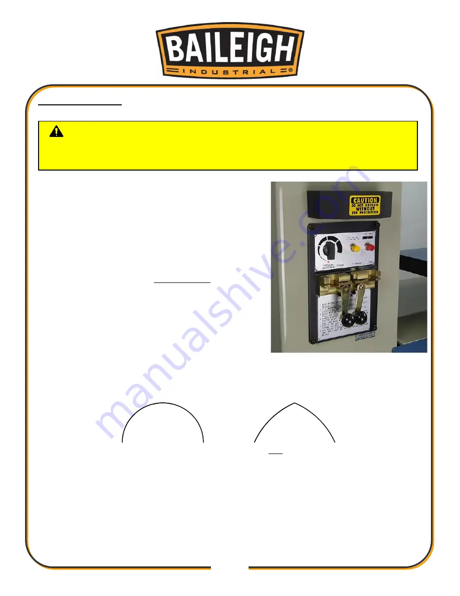
2.  Turn 

the weld force selector knob to “0” as shown in 

(fig. 23). 

3.  Clamp the saw band in the jaws making sure to 

carefully center the weld. It is still brittle. 

4.  Press the yellow annealing button quickly with a few 

short bursts to make the weld area a dull orangish-
red. (The wider the blade, the more bursts and time it 
will take.) After reaching a dull orangish-red, allow 
the area to cool 15-30 seconds and then repeat the 
heat twice more. 

Too much heat can damage the 

temper or burn through and destroy the weld. 

5.  After welding and tempering the blade, test the strength and 

flexibility


of the saw band by bending it in an arc similar to the pulley on the saw. 


CAUTION:

 The bandsaw blade is sharp and can cut your hand or fingers. 

Heat from the welding and annealing process can cause severe burns. Always wear 
leather gloves when working near the blade. 

Bend Like This

Not Like This

figure 23 

Summary of Contents for BSV-24VS

Page 1: ...AL HOLDINGS LLC IS PROHIBITED Baileigh Industrial Holdings LLC Inc does not assume and hereby disclaims any liability for any damage or loss caused by an omission or error in this Operator s Manual re...

Page 2: ...ulley with Adjustable Brush 16 Tilting Work Table 16 Upper and Lower Blade Guides 16 Fence and Miter Guide 17 Transmission Shift Lever 17 Variable Speed Hand Wheel 17 ELECTRICAL 18 BEFORE EACH USE 20...

Page 3: ...nsion Adjustment Wheel 34 Changing a Blade 35 Blade Tracking 36 LUBRICATION AND MAINTENANCE 37 Oil Disposal 38 Gearbox Maintenance 38 Disconnect Power from the Saw 38 Grease Fitting Locations 38 Blade...

Page 4: ...n notice to Seller of any suspected defect in the Goods prior to the expiration of the warranty period The original end user must also obtain a RGA from Seller prior to returning any Goods to Seller f...

Page 5: ...emedies provided under this Agreement or at law or equity Attorney s Fees In the event legal action is necessary to recover monies due from Buyer or to enforce any provision of this Agreement Buyer sh...

Page 6: ...Description of the functional parts of the machine Capacity charts Setup and start up instructions Machine operation Scheduled maintenance Parts lists GENERAL NOTES After receiving your equipment remo...

Page 7: ...zardous situation which if not avoided will result in death or serious injury WARNING Indicates a hazardous situation which if not avoided could result in death or serious injury CAUTION Indicates a h...

Page 8: ...e or uncomfortable loud noises BEWARE OF CUT AND PINCH POINTS Moving saw blade may result in loss of fingers or limb DO NOT operate with guard removed Follow lockout tagout procedures before servicing...

Page 9: ...igh does not recommend or endorse making any modifications or alterations to a Baileigh machine Modifications or alterations to a machine may pose a substantial risk of injury to the operator or other...

Page 10: ...art that appears damaged Check for alignment and binding of moving parts that may affect proper machine operation 15 Observe work area conditions DO NOT use machines or power tools in damp or wet loca...

Page 11: ...1118 x 2235mm Shipping Weight 1300lbs 590kgs TECHNICAL SUPPORT Our technical support department can be reached at 920 684 4990 and asking for the support desk for purchased machines Tech Support handl...

Page 12: ...ge painted surfaces Follow manufacturer s label instructions when using any type of cleaning product After cleaning wipe unpainted metal surfaces with a light coating of quality oil or grease for prot...

Page 13: ...to the floor Level the machine so that all the supporting feet are taking the weight of the machine and no rocking is taking place Follow these guidelines when lifting crane or hoist Always lift and c...

Page 14: ...the precise placement of it to the mounting surface FLOOR This machine distributes a large amount of weight over a small area Make certain that the floor is capable of supporting the weight of the ma...

Page 15: ...12 12 Footprint Dimensions...

Page 16: ...13 13 GETTING TO KNOW YOUR MACHINE F K B J A D G E C O H I M L N P...

Page 17: ...k piece J Work Lamp Provide additional light to the cut area K Blade Tension Adjustment Turn to incease or decrease blade tension L Air Tube Provide air to the work site to blow chip away from cut are...

Page 18: ...eld station It will cut saw bands ranging in width from 0 062 to 1 1 6mm to 25 4mm and thickness of 0 025 to 0 035 0 63mm to 0 89mm Weld Station Jaw clamp handles Stationary jaws Movable jaws Weld but...

Page 19: ...lting Work Table Located under the work table are the angle adjusting bolts As the table is tilted the angles can be read on the graduated scales Upper and Lower Blade Guides The blade guides provide...

Page 20: ...ions and is used together with the variable speed hand wheel to vary the speed of the blade as required for the material to be cut The neutral setting is useful during adjustment and maintenance funct...

Page 21: ...indicated on the machine All line connections should make good contact Running on low voltage will damage the motor In the event of a malfunction or breakdown grounding provides a path of least resist...

Page 22: ...ted below LENGTH AMP RATING 25ft 50ft 100ft 1 12 16 16 14 13 16 14 12 12 17 20 12 12 10 21 30 10 10 No WIRE GAUGE An undersized cord decreases line voltage causing loss of power and overheating All co...

Page 23: ...the cut off piece can move sideways after it is cut off Otherwise it could get wedged against the blade and thrown violently Never turn the saw ON before clearing everything except the work piece ben...

Page 24: ...s approximately 300cm of the material should be cut for breaking in If large work piece dimensions are to be cut we recommend a breaking in period of about 15 minutes After breaking in you may slowly...

Page 25: ...easured from gullet to gullet G GAUGE The thickness of the blade H TOOTH SET The distance a tooth is bent from the blade I KERF The width of material that is removed by the blade when cutting Width of...

Page 26: ...G A SAW BLADE A general purpose blade is furnished with this band saw To achieve a quality economical and efficient saw cut the following points must be taken into consideration Type of material being...

Page 27: ...24 24...

Page 28: ...ides Forcing a large width blade to cut a small radius Using a blade with an improperly finished weld joint Allowing the blade to run when not in use NEVER leave an unattended blade running MATERIAL S...

Page 29: ...tton to energize the motor stating the blade The saw blade should now be moving If any abnormal sounds or vibrations are noticed press the red stop button immediately 8 Adjust the variable speed C unt...

Page 30: ...e and welded to the right blade end Remove the blade from the jaws if any weld flash is present and carefully grind it off The blade joint must now be placed back into the jaws where annealing of the...

Page 31: ...it up Take small cuts so as not to overheat the blade band To get both ends of the band to match perfectly twist it and hold the ends so that the teeth are on opposite sides and pointing in opposite d...

Page 32: ...ockwise cw to the start or 0 position fig 20a 4 After squaring the ends of the blade insert each half until centered between the clamps fig 19 5 Secure the blade by raising the handles Check that the...

Page 33: ...try backing off on the weld force setting WARNING Sparks from the blade welding operation can be thrown in all directions and can cause serious personal injury or fire When using the blade welder alwa...

Page 34: ...s to make the weld area a dull orangish red The wider the blade the more bursts and time it will take After reaching a dull orangish red allow the area to cool 15 30 seconds and then repeat the heat t...

Page 35: ...ntain the blades actual thickness This will then allow the blade to pass through the guides without any obstructions 2 DO NOT burn or overheat the weld area when grinding CAUTION The bandsaw blade is...

Page 36: ...up to but not touching the back end of the blade Re tighten socket capscrew B 6 Next the blade needs to be centered between the blade guides To do this first loosen the socket capscrews C using a 5mm...

Page 37: ...can cause the blade to break To check the blade tension you can use a blade tensioner if available or by hand as explained below To properly tension the blade follow the procedure below 1 DISCONNECT...

Page 38: ...blade guards and through the slot in the table 7 Install the new blade in the reverse order 8 Make sure the back edge of the blade is next to but not touching the flange of the top sheave If the blade...

Page 39: ...a tracking issue occurs adjust the top sheave When the blade band is tracking towards the flange 1 Loosen the 4 bearing plate mounting bolts 2 Back out the top 2 jack screws a bit 3 Re tighten the 4...

Page 40: ...chanisms or may inflict injury to yourself or others Use compressed air to clean the blade guides Inspect the grinding wheel for wear Monthly Maintenance Check the blade guides and blade support for w...

Page 41: ...Remove the drive access panel 2 Remove the oil drain plug N and drain the oil into a catch basin Loosening oil fill plug O will help oil to drain 3 After draining replace drain plug N 4 Remove the fil...

Page 42: ...of grease to the pivot mechanism as necessary Tension Block Slide Apply grease to the sliding tension block as needed to keep it moving freely Table Support Lubrication Grease the pivoting table suppo...

Page 43: ...ligned guides Cracking of blade weld Adjust to where blade just does not slip on wheel Consult machine chart or handbook Adjust the wheel alignment Contact Baileigh Industrial for recommended blade ty...

Page 44: ...y from wheel flanges Adjust table to be square with blade Reduce pressure Increase blade tension a little at a time Move guide approx 25 6 3mm to piece part Replace blade Check manual for recommended...

Page 45: ...the blade tension Unusual Wear on Side Back of Blade Blade guides worn Blade guides not adjusted properly Blade guide bearing bracket is loose Replace blade guides Adjust as per operator s manual Tigh...

Page 46: ...43 43 NOTES...

Page 47: ...44 44 NOTES...

Page 48: ...TOWOC WI 54220 PHONE 920 684 4990 FAX 920 684 3944 www baileigh com BAILEIGH INDUSTRIAL HOLDINGS LTD UNIT D SWIFT POINT SWIFT VALLEY INDUSTRIAL ESTATE RUGBY WEST MIDLANDS CV21 1QH UNITED KINGDOM PHONE...

Reviews: