Nova-243 Outdoor LTE TDD Base Station Installation Guide
2
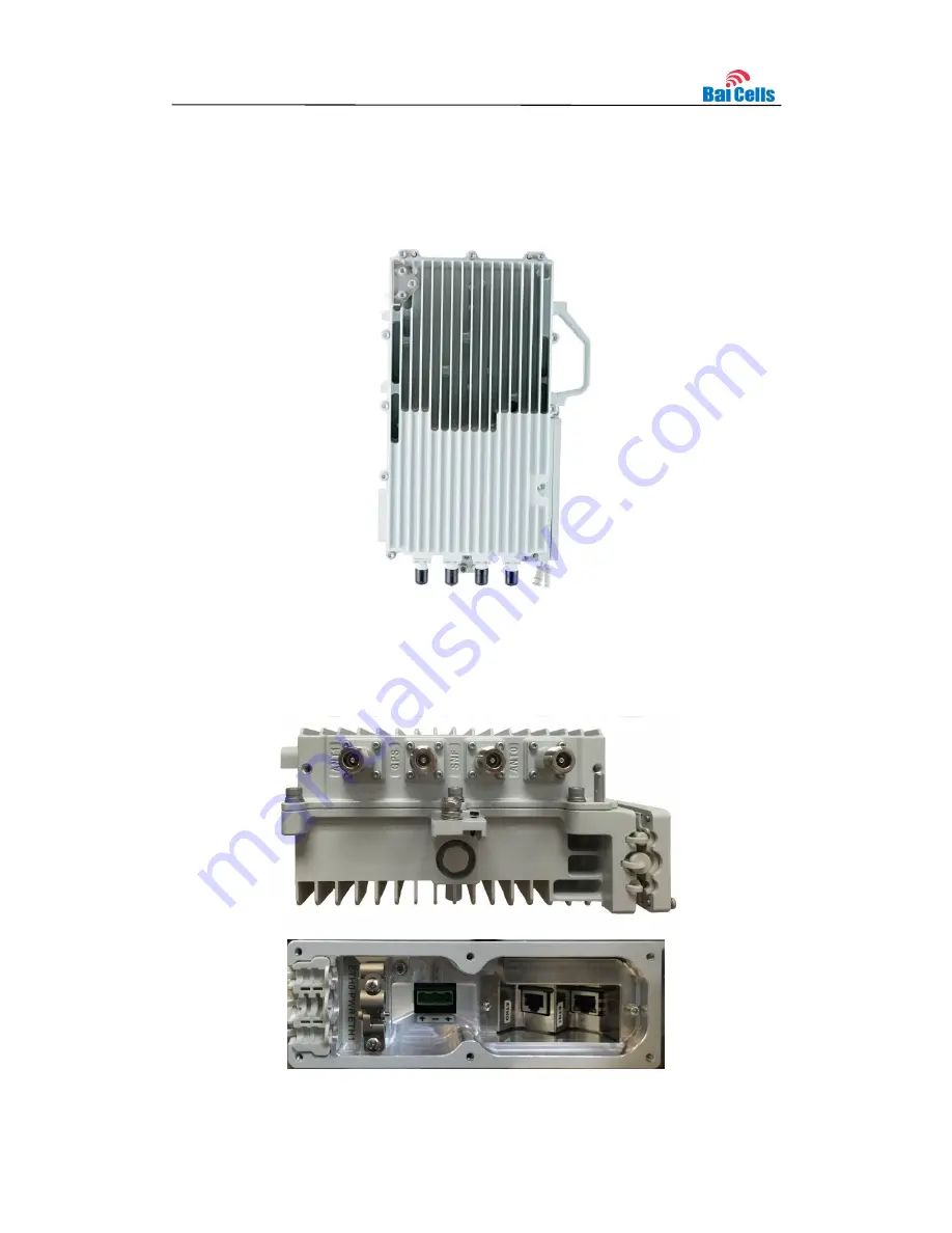
Appearance
1.3
The Nova-243 base station appearance is shown in Figure 1-1.
Figure 1-1 Nova-243
Appearance
The Nova-243 interfaces and indicators are shown in Figure 1-2.
Figure 1-2 Nova-243
Interfaces and Indicators


