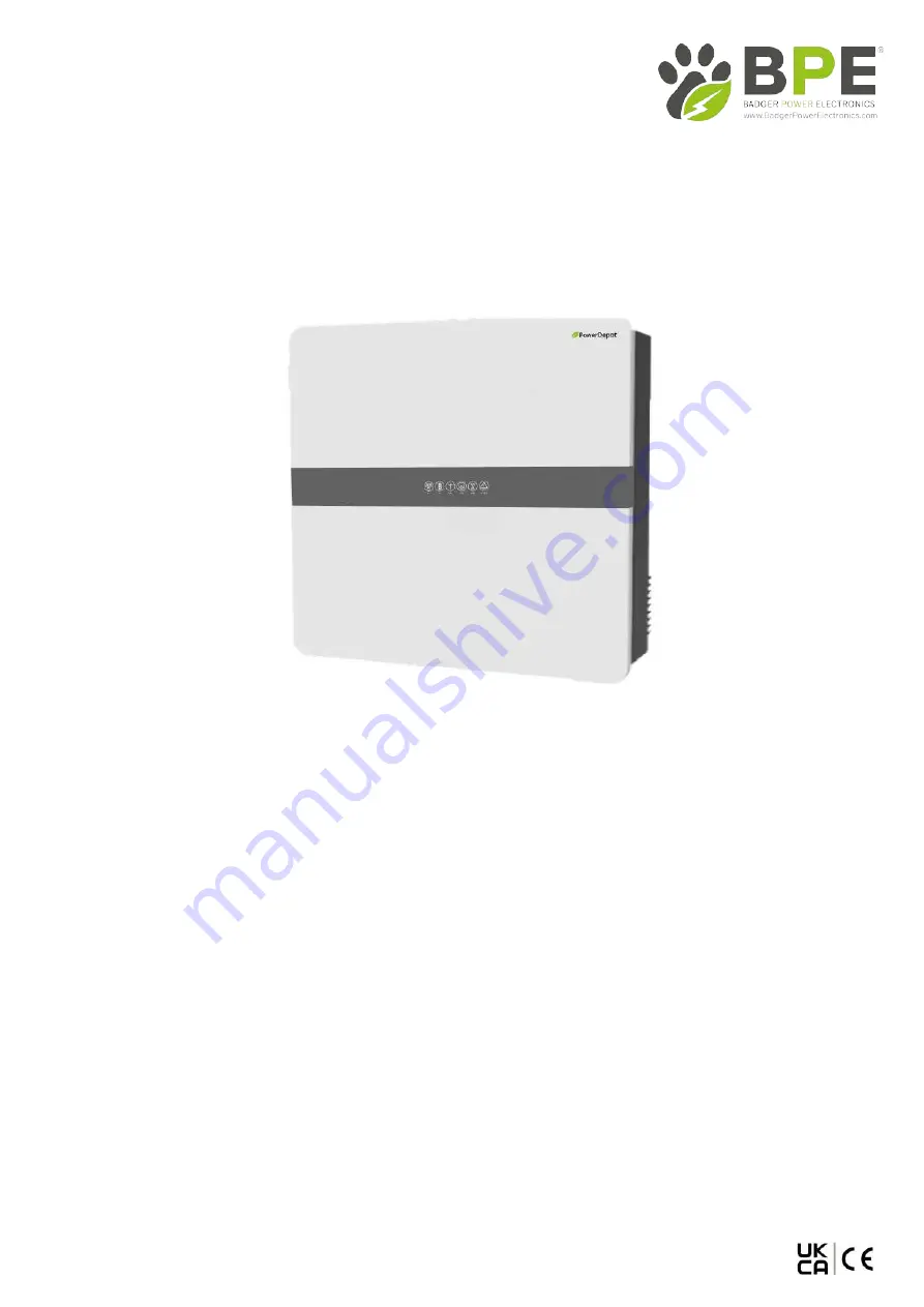
PowerDepot Hybrid Inverter
3.6kW/5.5kW
User Manual
V1.0
Badger Power Electronics
Address:
Manchester Science Park, Enterprise House, Lloyd
Street N, Manchester, M15 6SE, United Kingdom
www.
badgerpowerelectronics
.com
Page 1: ...Depot Hybrid Inverter 3 6kW 5 5kW User Manual V1 0 Badger Power Electronics Address Manchester Science Park Enterprise House Lloyd Street N Manchester M15 6SE United Kingdom www badgerpowerelectronics...
Page 2: ...4 Meter CT Connection 2 5 Communication Connection 2 6 Meter CT Communication Connection 2 7 RS485 Connection 2 8 NTC RMO Dry Connections 15 19 19 20 15 21 2 9 Wi Fi Datalogger Connection 3 Commission...
Page 3: ...id Inverter combines Solar PV Battery Charging and Emergency Backup Power together with an easy to use Bluetooth App to manage your home s complete power needs 25 24 6 5 2 1 9 10 11 12 3 4 Monitoring...
Page 4: ...ttery Type Lithium Lead acid Nominal Battery Voltage 48V Battery Voltage Range 40V 60V Max Charge Discharge Current 120A 120A Max Charge Discharge Power 3680W 3680W 5500W 5500W Lithium Battery Charge...
Page 5: ...ominal Output Current 16A 25A Transfer Time 10ms typ 20ms max THDV 3 100 R Load Certifications Grid VDE AR N4105 IEC 61727 62116 AS 4777 2 EN 50549 1 2019 C10 11 G98 G99 CEI 0 21 NRS 097 2 1 RD 1699 6...
Page 6: ...6 5 5 5 25 4 3 USB PARAL RS485 DRM BMS CT METER Lithium battery lead acid battery PE Normal Load Main Breaker Critical Load PE 2 BMS communication connection is only for lithium battery 3 Meter is opt...
Page 7: ...Grid EPS Connector A Diameter 14 20 10 14mm B Cross Section 8 14 4 6mm C Strip Length 10mm A B C Ensure you use the proper cables that are mandated by your local regulations Tighten all three screws...
Page 8: ...e MC4 connectors Negative Connector Diameter 4 6mm Limit buckle 4mm 4mm Click Note DC cables should be dedicated PV cables suggest using 4 6mm PV1 F cable Tighten the waterproof nuts on each connector...
Page 9: ...ed for maintenance The connection diagram when using a meter is as shown in the figure below 5 6 24 25 2 1 9 9 0 11 12 3 4 L N L N Grid Load BAT PV GRID EPS COM ALARM Please refer to the meter instruc...
Page 10: ...ce Description USB For USB communication upgrade LAN For ethernet communication upgrade BMS Lithium battery communication interface DRM Demand response mode METER CT For Meter CT communication 9 Pins...
Page 11: ...nut 1 2 3 1 3 2 Badger Power Electronics DRMs Connection DRMs is a shortened form for inverter demand response modes It is a compulsory requirement for inverters in Australia DRMs Control Module Rubbe...
Page 12: ...verter side Don t cut off any communication cables Unscrew the waterproof cover and loosen the rubber nut on waterproof cover Make the RJ45 terminal according to above function description of each Pin...
Page 13: ...terminal according to above function description of each Pin definition Lead the RS485 cable through the rubber nut seal and waterproof cover in turn Press the RS485 cable in the seal via the side in...
Page 14: ...aded sleeve fasten the rubber nut and screw the waterproof cover back to inverter firmly with 4 x M4 screws 1 2N m c c G S L H 1 2 3 4 5 6 7 8 9 Rubber nut Threaded sleeve NTC RMO DRY cable s Waterpro...
Page 15: ...k Mode menu and select the Self Used Mode work mode Under Self Used Mode the priority of PV energy will be Load Battery Grid that means the energy produced by PV gives priority to local loads excess e...
Page 16: ...rid Charge End can be set When the battery capacity reaches the set value of Capacity of Grid Charge End the grid will stop charging the battery 3 1 2 Feed in Priority Mode Go to the Hybrid Work Mode...
Page 17: ...ARM 3 1 4 Back up Mode Go to the Hybrid work mode menu and select the Back up Mode working mode Under this mode the priority of PV energy will be Battery Load Grid This mode aims at charging the batte...
Page 18: ...gy transmission 2 BAT PV GRID EPS COM ALARM Allow Grid Charging In this situation the battery can be charged both with PV and grid a Excess PV power When there is plenty of PV energy PV charges the ba...
Page 19: ...the above aspects are correct then follow the procedure below to start up the inverter 1 Power on PV 2 Power on the Battery 3 Power on the AC 4 Power on the EPS 5 Connect the SolarHope App via Blueto...
Page 20: ...t is normal Blink On Blink PV input is abnormal Off Off On On On Blink Blink Off Off On Off Blink Off PV is unavailable Battery is charging Battery is discharging Battery is abnormal Battery is unavai...
Page 21: ...e Play store The App will need access to some permissions such as device s location to function correctly 4 2 2 App Architecture Local connection The SolarHope App receives data from inverter through...
Page 22: ...want to connect Can not find Inverter code Inverter List Scanning machine SN barcode If you cannot recognize or have no barcode select Enter SN or Manual connection Remember Password LOGIN Account na...
Page 23: ...5 Step3 Set parameters for the inverter to connect to the power limit Power control Meter location Meter Type Power flow direction Digital meter modbus address Maximum feed in grid power W Next Previo...
Page 24: ...or load consumption or feed in grid Colour Purple Definition Consumption power from grid Colour Purple Definition Feed in grid power from PV or Battery Colour Orange Definition Home loads Colour Orang...
Page 25: ...power supported by grid Load consumption power 2 Monthly Inverter Data Go to Chart Month page It will show the Monthly Production or Consumption Curve in this page You can swipe the screen left and r...
Page 26: ...tion Software incompatibility 19 1kWh 53 0 47 0 CTIVE To Grid 8 97kWh Consumption 9 87kWh 76 0 24 0 From Grid 2 37kWh Self used mode Current Power 2 71kW CC Cons tly 10 1kWh INA umed direc CANCEL Clic...
Page 27: ...0 24 0 Current Power 2 71kW In this page you can view the basic information such as firmware versions and preform some maintaining operations like turn off on the inverter and manage data STE INV HB46...
Page 28: ...ing Grid Parameters Go to Console Grid Parameters page In this page you can set or change the parameters of Grid side as shown in the figure Feature Parameters Go toConsole Feature Parameterspage In t...
Page 29: ...e you can set or change the Reactive Power Control parameters Other Setting Go to Console Other Settingpage In this page you can set other setting parameters Enable Buzzer On to open the Buzzer functi...
Page 30: ...Maintenance Interval PV inverter cleaning PV inverter running status PV inverter electrical connections Statistically maintain the status of electrical yield and remotely monitor its abnormal status...
Page 31: ...Badger Power Electronics 5 2 System Troubleshooting 31...
Page 32: ...ND cable as shown below Step 2 Remove the inverter from the mounting bracket Before removing DC input connector double check DC input switch is turned to OFF to avoid inverter damage and personal inju...