Badger Meter SDI Series User Manual Download Page 7

MECHANICAL INSTALLATION

The accuracy of flow measurement for all insert type flow measuring devices is highly dependent on proper location of the 

sensor in the piping system . Irregular flow velocity profiles caused by valves, fittings, and pipe bends, can lead to inaccurate 

overall flow rate indications even though local flow velocity measurement may be accurate . A sensor located in the pipe that 

is partially full or where it can be affected by air bubbles, floating debris, or sediment may not achieve full accuracy and could 

be damaged . 
Data Industrial flow sensors are designed to operate reliably under adverse conditions, but the following recommendations 

should be followed to ensure maximum system accuracy:
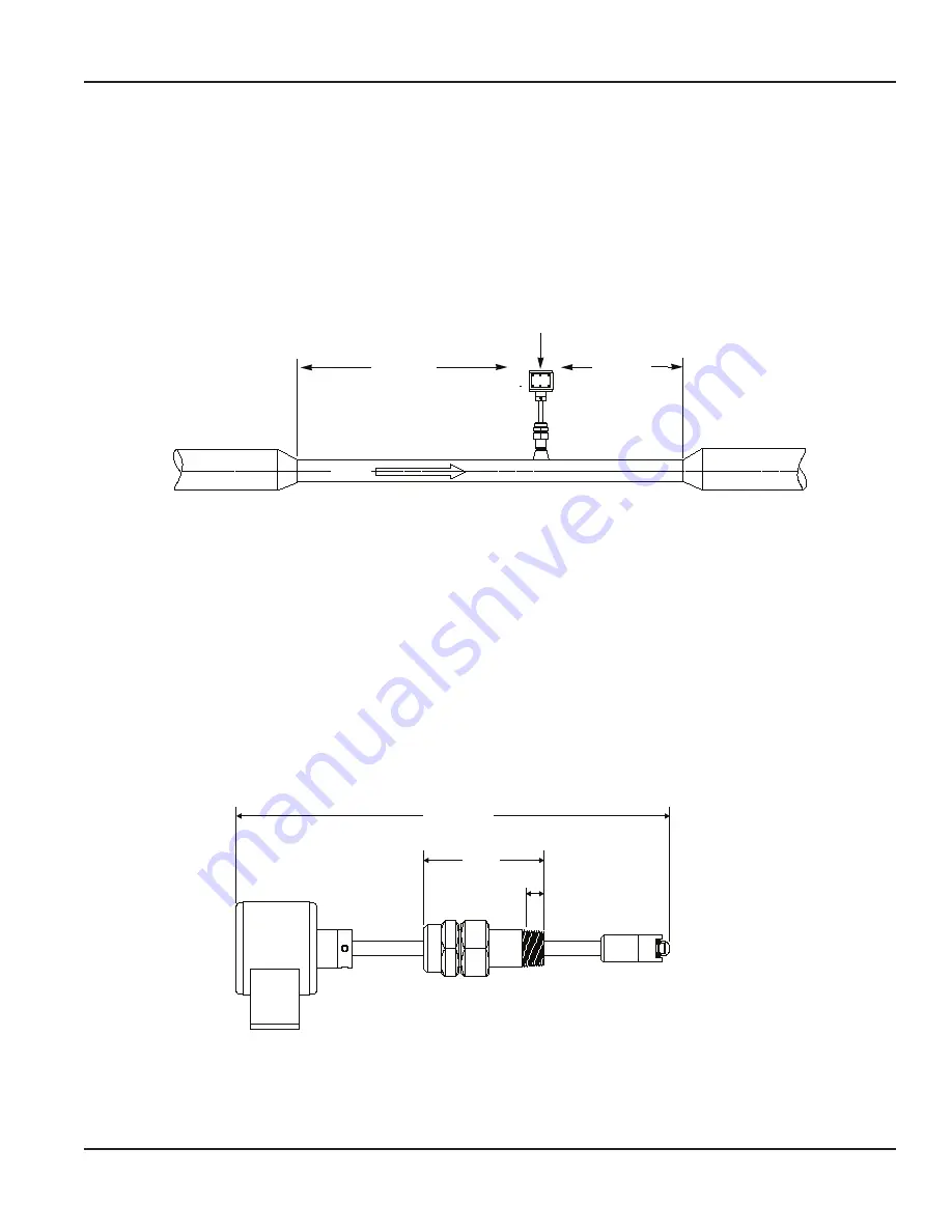
5 x Pipe Dia

DATA INDUSTRIAL

SDI Series Sensor

10 x Pipe Dia

FLOW

Figure 2:  Minimum recommended straight run distance

1 .  Choose a location along the pipe where there is straight pipe for a distance of ten pipe diameters upstream and five pipe 

diameters downstream of the sensor . Pipe bends, valves, other fittings, pipe enlargements and reductions or anything else 

that would cause a flow disturbance should not be present in this length of pipe .

2 .  The recommended tap location around the circumference of a horizontal pipe is on top . If trapped air or debris will 

interfere, then the sensor should be located around the pipe from the top preferably not more than 45 degrees from 

top dead center . The sensor should never be located at the bottom of the pipe, as sediment may collect there . Locations 

off top dead center cause the impeller friction to increase, which may affect performance at low flow rates . Any 

circumferential location is correct for installation in vertical pipes .

3 .  Insertion depth is critical to accuracy . The algorithm used to convert impeller motion into flow was developed through 

flow tests in an independent calibration laboratory . The impeller must be located in the same position in the pipe as it 

was in the calibration test for the impeller frequency to accurately describe the same liquid velocity . Detailed installation 

instructions on the following pages include methods for ensuring correct insertion depth .

4 .  Alignment of the sensor is also important . The impeller shaft must be perpendicular to the flow for accuracy . Alignment 

instructions are also included on the following pages .

D1=15 3/4”

D2=19”

4.23”

0.660”

Handtight Enga Wrench Makeup

Per ANSI/ASME B1.20.1-1993, R1992

D1 is for pipe sizes 1½” - 10” *

D2 is for pipe sizes 12” - 36” *

* Pipe sizes are for reference only - Depending on pipe material, tapping 

saddle, or existing hardware a longer sensor length may be required, 

Consult Factory.

Figure 3:  Direct insertion sensor dimensions

Mechanical Installation 

Page 7 

May 2017

SEN-UM-00217-EN-10

Summary of Contents for SDI Series

Page 1: ...Flow Sensors Insert Style Flow Sensors SDI Series Battery Powered SEN UM 00217 EN 10 May 2017 User Manual...

Page 2: ...Flow Sensors Insert Style Flow Sensors SDI Series Battery Powered Page ii May 2017 SEN UM 00217 EN 10...

Page 3: ...d Ordering Matrix 6 Display Options 6 Mechanical Installation 7 Installation for Direct Insert Models 8 Installation for Hot Tap models 10 Programming 15 Customer Reference Number Tables 17 K Offset T...

Page 4: ...Flow Sensors Insert Style Flow Sensors SDI Series Battery Powered Page iv May 2017 SEN UM 00217 EN 10...

Page 5: ...rue hot tap installation the sensor is mounted in the pipe under pressure by attaching a service saddle or weld on fitting to the pipe and mounting the isolating valve and nipple to the threaded conne...

Page 6: ...R Stainless Steel 0 BEARING Torlon 0 Figure 1 Battery operated ordering matrix Pipe size for reference only Depending on pipe size tapping saddle or existing hardware longer sensor length may be requi...

Page 7: ...ebris will interfere then the sensor should be located around the pipe from the top preferably not more than 45 degrees from top dead center The sensor should never be located at the bottom of the pip...

Page 8: ...1 is intended for nominal pipe diameters from 1 1 2 10 in 38 254 mm and the D2 for pipe diameters from 12 36 in 30 91 cm However pipe with extra thick walls existing linings or unusual tapping hardwar...

Page 9: ...r along the shaft until its bottom surface is at the mark on the stem Tighten the cap screw on the collar When the sensor is reassembled this will set the insertion depth of the sensor 5 Attach the se...

Page 10: ...ipe diameters from 12 36 in 30 91 cm and stem length H3 is for nominal pipe diameters from 36 in and up However pipe with extra thick walls existing linings or unusual tapping hardware may require lon...

Page 11: ...ded for drilling through a 1 in ball valve cannot be used 6 Attach the tapping machine to the tapping adapter Ensure that all connections and seals are tight 7 Slowly open the valve by rotating the ha...

Page 12: ...e pipe by pushing against the top of the electronics housing with a slight twisting motion until the stem collar meets the cover The force required to push the sensor into the pipeline is approximatel...

Page 13: ...ensor accessible by removing the side cover battery holder The battery is held in a spring clip attached to the cover The required battery is a 3V lithium C size that can be purchased through Badger M...

Page 14: ...is an open collector transistor closure with a maximum sinking current of 100 mA The cable that plugs into the existing pigtail from the PC board is PN 807021 Power Connector Attach DI 3V Lithium only...

Page 15: ...ect the PC to the SDI with the ASDIB 20 SDI programming kit Plug in the RJ11 plug from the ASDIB 20 kit to the RJ11 socket on Battery Powered SDI Connect the DB9 connector of the ASDIB 20 kit to the P...

Page 16: ...progress It may take up to 1 1 2 minutes to program the Battery Powered SDI When the status bar says updated the Battery Powered SDI is programmed NOTE 2 N After you press Exit it takes about 10 seco...

Page 17: ...1 73 3 1 32 0 316 1 83 3 1 32 8 in 8 625 Wall Insertion Depth Customer Ref 0 148 2 50 3 17 32 0 148 2 50 3 17 32 0 322 2 39 3 19 32 0 322 2 39 3 19 32 0 500 2 29 3 21 32 0 410 2 40 3 11 16 10 in 10 7...

Page 18: ...8 1 7 16 0 060 0 49 1 7 16 0 049 0 50 1 7 16 0 042 0 51 1 7 16 2 in 2 125 Wall Insertion Depth Customer Ref 0 083 0 72 1 11 16 0 070 0 73 1 11 16 0 058 0 74 1 11 16 0 042 0 76 1 11 16 2 1 2 in 2 625 W...

Page 19: ...6 8 in 9 050 Wall Insertion Depth Customer Ref 0 362 2 50 3 23 32 10 in 11 100 Wall Insertion Depth Customer Ref 0 444 3 06 4 3 8 12 in 13 200 Wall Insertion Depth Customer Ref 0 528 3 64 5 1 16 For o...

Page 20: ...2 681251 15 359217 2 681251 14 116608 2 693176 14 116608 2 693176 12 779132 2 904373 12 779132 2 904373 12 in 12 750 K Offset 22 687525 5 074024 22 687525 5 074024 22 492687 4 969576 22 492687 4 96957...

Page 21: ...fset Ductile Iron Because of the variety of iron pipe classes sizes and wall thicknesses consult the factory for customer reference number Pipe O D Schedule or pipe O D I D or Pipe O D and wall thickn...

Page 22: ...38 mm diameter and up Accuracy Standard to 1 of rate over optimum flow range Straight Pipe Requirement Install sensor in straight pipe section with a minimum distance of 10 diameters upstream and 5 d...

Page 23: ...a Short Circuit Current 50 mA typical n a 100 mA For direction 100 mA 100 mA 100 mA Output Frequency 800 Hz max n a Scaled by customer n a Scaled by customer Scaled by customer Output Pulse Width 5 m...

Page 24: ...Inn CP 01050 M xico DF M xico 52 55 5662 0882 Europe Eastern Europe Branch Office for Poland Latvia Lithuania Estonia Ukraine Belarus Badger Meter Europe ul Korfantego 6 44 193 Knur w Poland 48 32 236...

Reviews: