


Test Procedures
OTE:
N
This test can be repeated for the reverse direction
Motor Test Simulated Load
1 Reverse the pump flow
2 Open the Hydraulic System Analyzer loading valve fully to read maximum pump flow at zero pressure
3 Install one or both of the following instruments on the hydraulic motor
a Place a Hedland Variable Area Flow Meter¹ on the case drain and manually record the flow as you increase the load on
the tester Then compare it to the manufacturer’s specifications
b Place a tachometer on the motor’s shaft
4 Select
Run
and/or
Record
on the PC (see
"Recording Measurements to a File" on page 10
)
5 Increase the load on the Hydraulic System Analyzer to produce back pressure on the hydraulic motor
WARNING
SEE MANUFACTURER'S SPECIFICATIONS FOR MAXIMUM ALLOWABLE BACK PRESSURE. IF THE MOTOR DOES NOT
HAVE AN EXTERNAL DRAIN, IT CANNOT HAVE A BACK PRESSURE LOAD. FAILURE TO FOLLOW THE MANUFACTURER'S
SPECIFICATIONS CAN RESULT IN INJURY TO PERSONNEL AND/OR DAMAGE TO THE EQUIPMENT.
6 The flow at rated RPM can now be checked against the motor manufacturer’s specifications A decrease in RPM and an
increase of case flow with increased load indicates a loss of the motors efficiency
OTE:
N
If the flow and RPM meet specifications, it could indicate a relief valve problem or DCV problem
¹ For complete information, visit www badgermeter com and select Petroleum Fluids under Products / Variable Area High
Pressure Flow Meters
Directional Control Valve (DCV) Test
1 Isolate the motor from the circuit and connect the Hydraulic System Analyzer’s output to the DCV’s B port
2 Select
Run
and/or
Record
on the PC (see
"Recording Measurements to a File" on page 10
)
3 Slowly close the Hydraulic System Analyzer loading valve to achieve the rated pump pressure Repeat for all operating
positions of all DCV’s
◊ If all components are in good operating condition, pressure and flow measurements should be the same as in the
Pump Test
◊ If a decrease in flow in any DCV position is noted, leakage is indicated
◊ If the decrease in flow is the same with the control valve in all positions, it indicates the relief valve is at fault
OTE:
N
This can also indicate some other leak is present in the control valve, such as a defective casting, damaged seals, or
worn valve position detents, but always check the relief valve FIRST
◊ If the flow readings are now higher and comparable to the other control valves, then a faulty cylinder or motor
is indicated
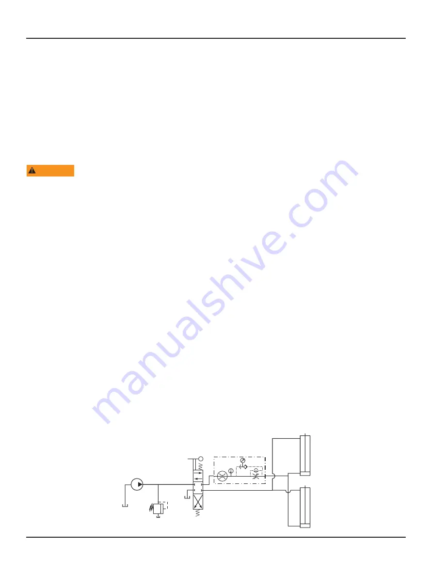
Bi-directional Cylinder Test
Use this setup to calculate extension times and verify force
Flo-Check
Figure 10: Bi-directional cylinder test
Page 22
June 2022
TST-UM-02433-EN-02