


4
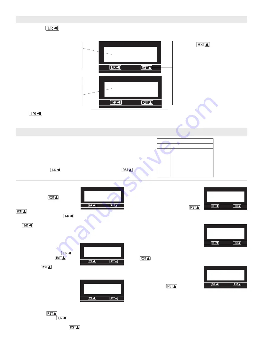
By pressing the
key during normal operation, the ER-10 will alternatively display the Flow Total or the
Flow Rate. The Letter R on the left indicates that the Flow Rate is being displayed.
Total Display:
Indicates the present
count value, which is equal to the
number of pulses received (since
the last reset) multiplied by the To-
talizer Scaler Value in Program mode
#1.
Rate Display:
Indicates the rate
value, which is equal to the input
frequency multiplied by the Rate
Prescale Value in Program Mode
#3. (If no pulses are received for 2
seconds, the rate value goes to
zero.)
When the program input is active (see
wiring) this key is used to select a menu
item for editing.
or
Reset Key:
If the total value is being displayed, de-
pressing this key will cause the value to
be reset to 0 as long as program mode #7
is preset accordingly.
Down Key:
Toggles the unit between the total and rate display. When the program input is
active this key is used to scroll through the menu items. After a menu item has been chosen
for editing, the down key is used to set the value for the currently selected (flashing) digit.
Operation
Programming
Mode #1:
Is used to enter the count
scale factor. The far right digit will be
flashing. Press the
key until
reaching the desired digit value.
NOTE:
pressing and holding the
key will cause the numbers
to autoscroll. Next press the
key to move the flashing digit
one place to the left. Change this digit to the desired value with
the
key. Repeat this process until all digits are set
correctly. (Setting the count scale factor to 00.0000 will allow
scaling by 100 in ER Series.)
Mode #2:
Is used to enter the
decimal point display on the totalizer
screen. Press and hold the
key and then press the
key to
move from screen one to screen
two. Press the
key to move
the decimal point to the desired position.
Mode #3:
Allows the user to enter
the rate scale factor. The lower case
"d" appears on the right of the
display when it is time to enter the
decimal point position for the rate
scaler.
NOTE:
This decimal point is
used for the rate scaler only and will not appear on the ratemeter
screen. Press the
key to chance the first digit to the
correct value. Press the
key to select the next digit to be
changed. Repeat this process untill all the digits are correct.
When the 'd' appears, press the
key until the decimal
point is in the desired location.
34675890
34675890
34675890
34675890
34675890
2345
2345
2345
2345
2345
R
To enter the program mode, a connection must be made between
terminals 1 and 5.
Programming Screens
Press and hold the
key while repeatedly pressing the
key
to advance to successive screens.
Pro
g
rammin
g
S
creen
s
S
creen
1
2
3
4
5
6
Function
Totalizer
S
cale Factor
Totalizer Decimal Point
Rate
S
cale Factor
Rate
S
cale Factor Decimal Point
Rate x1/x10
Re
s
et Key Enable/Di
s
able
1
1
1
1
1
01.0000
01.0000
01.0000
01.0000
01.0000
2 000000
2 000000
2 000000
2 000000
2 000000
3 0000
3 0000
3 0000
3 0000
3 0000
4 0000
4 0000
4 0000
4 0000
4 0000
5 1
5 1
5 1
5 1
5 1
6 r
6 r
6 r
6 r
6 r
Mode #4:
Is used to enter the
decimal point position for the
ratemeter run-mode display. The
display will show the screen number
(4) and four zero's. Press the
keyuntil the decimal point is in the
correct position.
Mode #5:
Is used to select the rate
display multiplier of one or ten.
Selecting rate x10 will add a zero to
the far right of the display. This zero
will not change value and does not
affect the decimal point. The display
will show the screen number (5) and a 1 at the right. Press the
keyto select 1 or 10.
Mode #6:
Is used to determine
whether the front panel reset key will
function. The screen will show a
number 6 on the left and an R on the
right. Press the
key to
choose the option you want.
(R - Reset, NoR - Non-Reset)
NOTE:
The reset terminal on the
rear panel is still active when the front reset button is disabled. To
exit the program mode, break the connection between terminals 1
and 5.


